Software aging test system, software aging test method, and program for software aging test

a software aging and test system technology, applied in the field of software aging test systems, software aging test methods, and software aging test programs, can solve the problems of software aging, system failure rate increase, program processing performance degradation, etc., and achieve the effect of reducing software development and reducing the precision of software aging detection

Inactive Publication Date: 2016-06-30
NEC CORP
View PDF10 Cites 15 Cited by
  • Summary
  • Abstract
  • Description
  • Claims
  • Application Information

AI Technical Summary

Benefits of technology

[0014]According to the present invention, load test can be executed with an appropriate frequency so that a decrease in software development due to high-frequency load test and a decrease in the precision of software aging detection due to low-frequency load test are avoided.

Problems solved by technology

Software aging is degradation of an execution environment of software due to prolonged continuous operation of the software.
Software aging progresses with time and leads to degradation of the program processing performance and an increase in the system failure rate.
Most of the software aging problems are caused by defects of software (bugs in programs).
A memory leak is a typical example of software aging which is caused by failure to release memory.
When such a defect is found after the release of the software, system operation can be compromised, leading to decrease in reliability.
However, such load test is costly and time consuming because the load test requires a provision of an experimental environment for executing the testing.
In particular, detection of software aging problems requires prolonged continuous operation and continuous monitoring.
For example, if the past version does not exhibit an upward trend in memory consumption while the current version exhibits an upward trend in memory consumption, it can be determined that the current version has a high probability of containing defects that can cause software aging.
Since the determination is made by comparison with past trends, signs of problems can be identified early before prolonged operation of the software.
Note that the term “software aging problem” as used in the description and the claims means the risk of software aging latent in software.

Method used


Image

  • Software aging test system, software aging test method, and program for software aging test
  • Software aging test system, software aging test method, and program for software aging test
  • Software aging test system, software aging test method, and program for software aging test

Examples


first exemplary embodiment

Description of Configuration

[0022]A first exemplary embodiment of the present invention will now be described in detail with reference to the drawings.

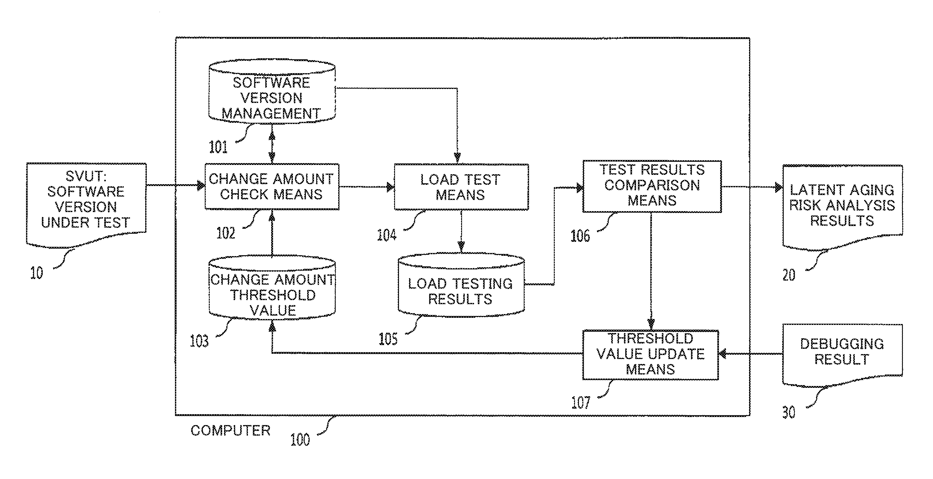
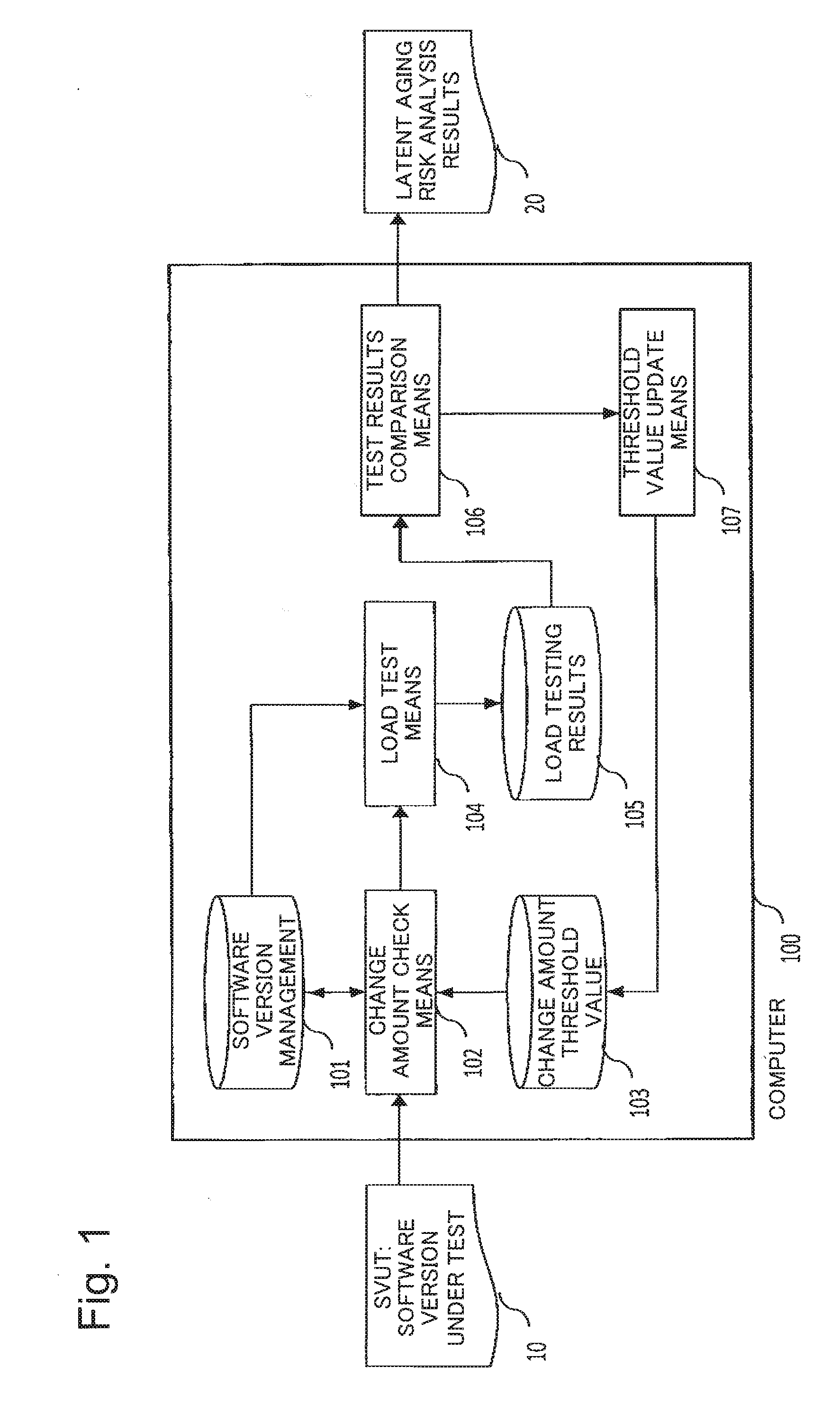
[0023]Referring to FIG. 1, in the first exemplary embodiment of the present invention, a version of software to be tested (also referred to as a software version under test (SVUT)) 10 is provided as an input to a computer (also referred to as a central processing unit, processor or data processing device)100 operating under the control of a program and results of latent aging risk analysis 20, which are results of analysis of aging risk latent in the software version under test, are output. The computer 100 includes a software version management storage device 101 which manages versions of software, a change amount check means 102 which checks an amount of change in a software version under test, a change amount threshold value storage device 103 which stores a change amount threshold value that serves as a criterion for determining w...

second exemplary embodiment

Description of Configuration

[0042]A second exemplary embodiment of the present invention will be described next in detail with reference to drawings.

[0043]Referring to FIG. 3, the second exemplary embodiment of the present invention differs from the first exemplary embodiment in that debugging result 30 is input in the threshold value update means 107 in the configuration of the first exemplary embodiment in FIG. 1 through debugging result input means (not depicted).

Description of Operation

[0044]The debug result input means of a computer 100 accepts an input of a result of debugging performed when a software aging problem has been detected, and sends the accepted result of debugging to the threshold value update means 107. On the basis of the result of debugging and a result of software aging detection acquired from test results comparison means 106, the threshold value update means 107 determines whether to update a threshold value.

[0045]Entire operation of this exemplary embodimen...

case 1

[0054]Consider a case where results in FIG. 6 have been obtained as a result of observation of changes in memory (Resident Set Size) consumed by the software during load test. Values observed in the software version under test (SVUT) and the latest good software version (LGV) and approximate curves obtained by linear regression analysis of the observed values are illustrated. As can be seen from the comparison between the slopes of the approximate curves, the slopes of the software version under test (SVUT) and the latest good software version (LGV) do not greatly differ from each other. Accordingly, it is determined in this case that software aging does not exist in the software version under test. For the determination, a specific difference threshold value may be used. For example, when the difference in change amount of the Resident Set Size is less than or equal to 2.0, it is determined that software aging does not exist. On the basis of this result, the threshold value update ...


PUM


Abstract

Load test is executed with an appropriate frequency which does not lead to a decrease in software development efficiency and a decrease in the precision of software aging detection. Load test of a version of software under test is executed in accordance with an execution criterion, presence or absence of a software aging problem is detected by comparing a test result of the load test with a test result of load test of a previous version of the software to be compared, and frequency of execution of subsequent load test is adjusted by changing the execution criterion based on a result of the detection.

Description

TECHNICAL FIELD[0001]The present invention relates to a software aging test system, a software aging test method, and a program for software aging tests and, in particular, to a software aging test system, a software aging test method, and a program for software aging tests that are capable of improving the efficiency of development of software.BACKGROUND ART[0002]Software aging is degradation of an execution environment of software due to prolonged continuous operation of the software. Software aging progresses with time and leads to degradation of the program processing performance and an increase in the system failure rate. Most of the software aging problems are caused by defects of software (bugs in programs). A memory leak is a typical example of software aging which is caused by failure to release memory. When such a defect is found after the release of the software, system operation can be compromised, leading to decrease in reliability. It is therefore desirable to eliminat...

Claims


Application Information

Patent Timeline
Patent Type & Authority Applications(United States)
IPC IPC(8): G06F11/36
CPCG06F11/368G06F11/3688G06F11/3409G06F11/3428G06F11/3433G06F11/3692G06F2201/81G06F2201/865
Inventor MACHIDA, FUMIO
Owner NEC CORP
Why Eureka
Try Eureka