
Gaze-contingent Display Technique

a technology of contingent viewing and content, applied in the field of system and method of displaying plenoptic still and video images, can solve the problems of high user acceptance of such systems, often too frequent refocusing as achieved by prior art techniques, and unsatisfactory user experien

Active Publication Date: 2016-06-30
VON & ZU LIECHTENSTEIN MAXIMILIAN RALPH PETER
View PDF6 Cites 49 Cited by
  • Summary
  • Abstract
  • Description
  • Claims
  • Application Information

AI Technical Summary

Benefits of technology

This patent—which describes a virtual reality system that puts the user in the center of a virtual sphere and uses a plenoptic image to fully immersse them—combines a technique called refocusing with foveated imaging to improve the overall three-dimensional viewing experience. The technique makes use of eye tracking capabilities to create a lifelike view without the need for stereoscopic viewing aids. The patent also provides a computer-readable medium with instructions for processing the plenoptic image to make it suitable for enhanced three-dimensional viewing. The key advantage of the refocusing technique is that it allows the user to selectively focus on a specific depth plane, resulting in a more immersive experience.

Problems solved by technology

One of the problems identified in the context of this invention is that refocusing as achieved by prior art techniques is often too frequent and thus leads to an unsatisfactory user experience.
A constantly shifting focus in instant response to even the slightest eye movement tends to be seen as very annoying by the average user and the user acceptance of such systems is accordingly rather low.
A particular problem materializes when during a display of a plenoptic video there is an abrupt change of scene.

Method used


Image

  • Gaze-contingent Display Technique
  • Gaze-contingent Display Technique
  • Gaze-contingent Display Technique

Examples


Embodiment Construction

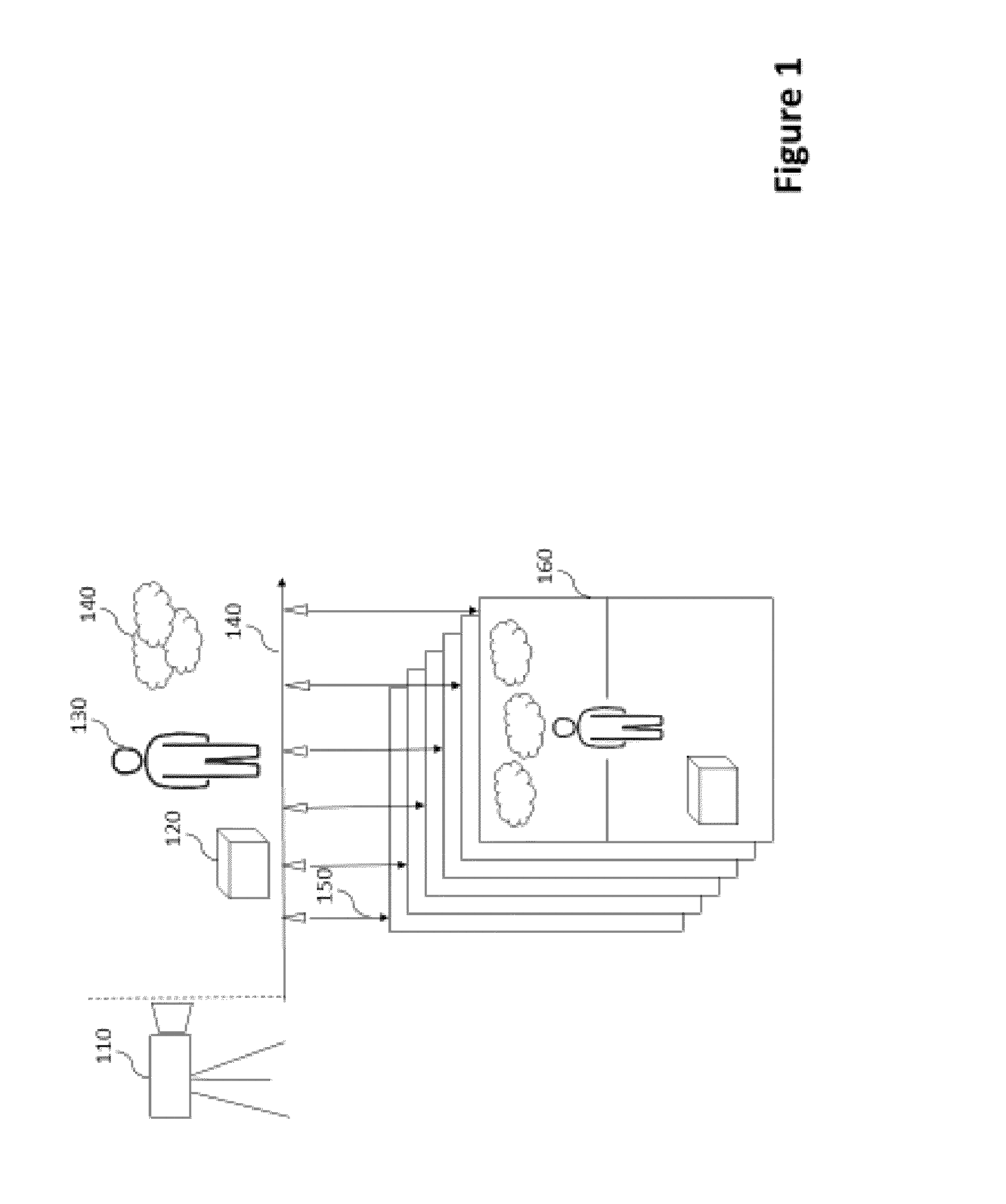
[0029]The prior art knows a technique of viewing light field images in a format named “editable living picture” which comprises a plurality of seven TIF format images in addition to a depth map, wherein a depth map comprises a layer of data that defines the distance of various surfaces from the lens of the camera, like a topographic map of that image. FIG. 1 depicts such a stack of images, each with its own focal length. The camera 110 is shown to capture three different objects 120130140, each at a different distance 140 from the camera.

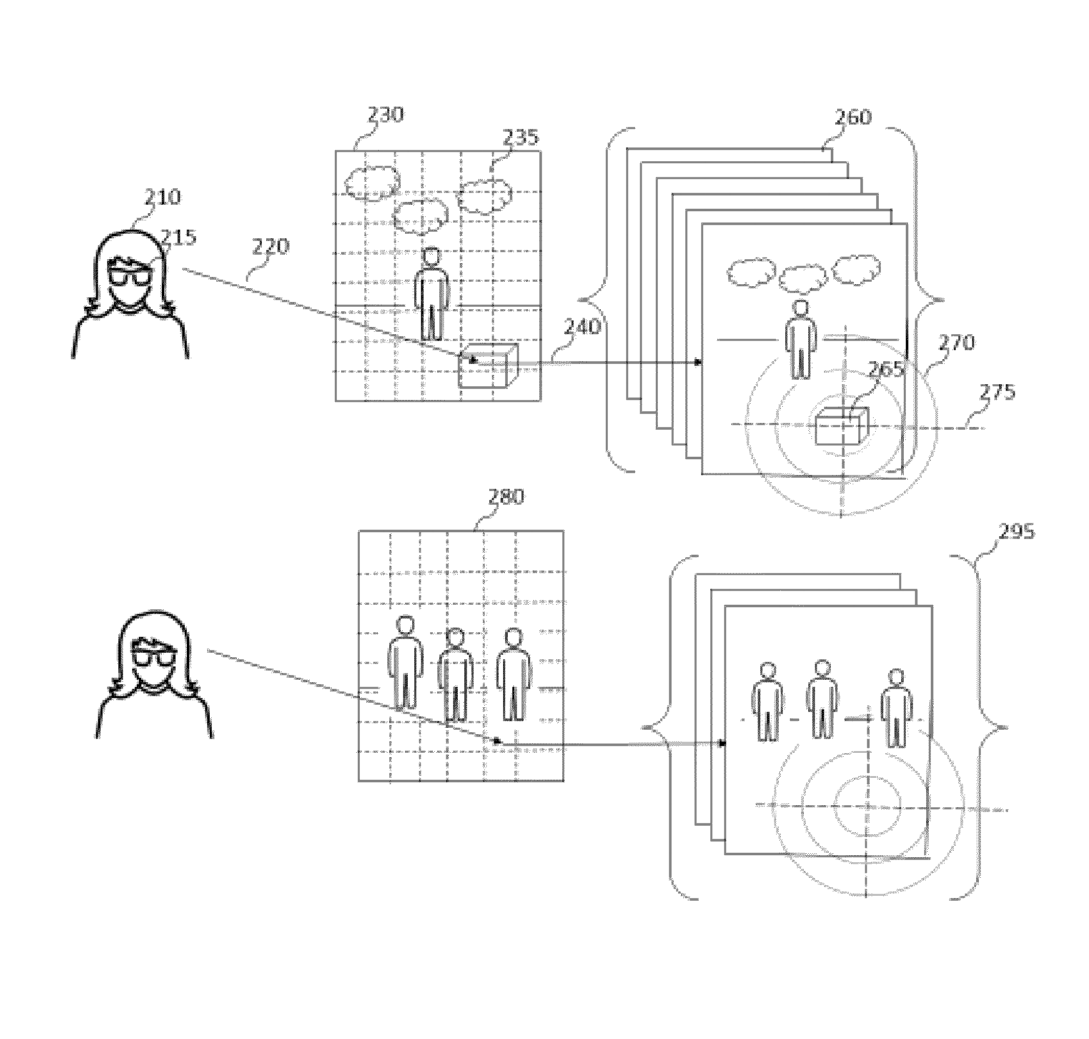
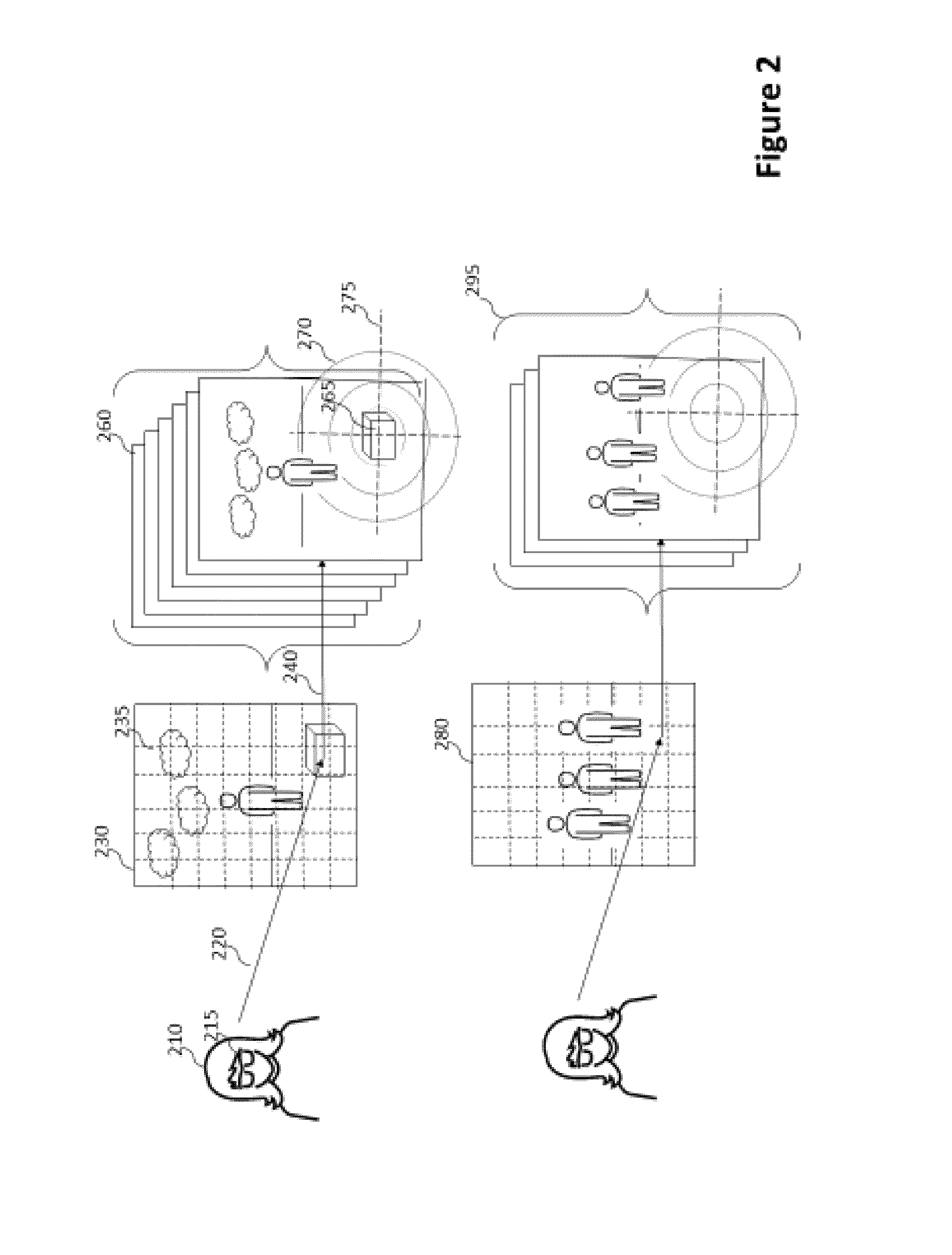
[0030]A mapping 150 maps each image to a specific focal depths. FIG. 2 depicts an embodiment of the present invention whereby a user 210 is wearing a head-mountable device 215 capable of tracking the user's gaze fixation 220 on an image 230 which comprises a depth map 235 wherein a grid is utilized to map 240 each grid element to a “living picture”-type image 260 of a specific focal depth. Whenever the user changes her gaze to a different image segm...


PUM


Abstract

A gaze contingent display technique for providing a human viewer with an enhanced three-dimensional experience not requiring stereoscopic viewing aids. Methods are shown which allow users to view plenoptic still images or plenoptic videos incorporating gaze-contingent refocusing operations in order to enhance spatial perception. Methods are also shown which allow the use of embedded markers in a plenoptic video feed signifying a change of scene incorporating initial depth plane settings for each such scene. Methods are also introduced which allow a novel mode of transitioning between different depth planes wherein the user's experience is optimized in such a way that these transitions trick the human eye into perceiving enhanced depth. This disclosure also introduces a system of a display device which comprises gaze-contingent refocusing capability in such a way that depth perception by the user is significantly enhanced compared to prior art. This disclosure comprises a nontransitory computer-readable medium on which are stored program instructions that, when executed by a processor, cause the processor to perform operations relating to timing the duration the user's gaze is fixated on each of a plurality of depth planes and making a refocusing operation contingent of a number of parameters.

Description

CROSS REFERENCE TO RELATED APPLICATIONS[0001]Not applicable to this application.STATEMENT REGARDING FEDERALLY SPONSORED RESEARCH OR DEVELOPMENT[0002]Not applicable to this application.BACKGROUND[0003]1. Field[0004]Example embodiments in general relate to systems and methods for displaying plenoptic still and video images, and more particularly to methods, systems and operations for displaying plenoptic content utilizing gaze contingent viewing techniques.[0005]2. Prior Art[0006]Any discussion of the related art throughout the specification should in no way be considered as an admission that such related art is widely known or forms part of common general knowledge in the field.[0007]With the advent of plenoptic imaging technology a considerable number of contributions to improved display devices have been made in recent years. In particular there have been vast advances in the field which combines eye-tracking sensors with the display of plenoptic images. Plenoptic technology allows...

Claims


Application Information

Patent Timeline
Patent Type & Authority Applications(United States)
IPC IPC(8): H04N13/04H04N13/00
CPCH04N13/0484H04N13/0029H04N13/0497H04N13/0018H04N13/0022H04N13/383G06F3/013H04N13/139H04N13/279
Inventor VON UND ZU LIECHTENSTEIN, MAXIMILIAN RALPH PETER
Owner VON & ZU LIECHTENSTEIN MAXIMILIAN RALPH PETER
Learn More