Method and Apparatus Useful for Transcatheter Aortic Valve Implantation

a technology for aortic valves and transcatheters, applied in the field of methods and apparatus useful for transcatheter aortic valve implantation, can solve the problems of difficulty in navigation, design compromise, and various difficulties in the transcatheter heart valve replacement procedure, and achieve the effect of reliable positioning and/or alignment of a prosthetic valv

Active Publication Date: 2016-07-07
BOSTON SCI MEDICAL DEVICE LTD
View PDF7 Cites 2 Cited by
  • Summary
  • Abstract
  • Description
  • Claims
  • Application Information

AI Technical Summary

Benefits of technology

[0010]The presence of a single guide catheter through which such other catheters and / or devices may be introduced, can reduce the risk of direct abutment and / or abrasive rubbing contact between the vasculature wall and each catheter / device being introduced or removed. This may be especially advantageous in the aortic arch, which may suffer from the double problem of heavy calcification and bending through 180 degrees, and inevitably involving contact with the vassal wall. Instead, the guide catheter acts as a sheath that can protect, at least to some extent, the vasculature wall. There may be only a single introduction stage, and a single removal stage, involving the guide-catheter itself, independent of the number of other devices / catheters introduced and removed via the guide catheter. Furthermore, use of a protective guide-catheter may reduce the severe atraumatic design constraints normally associated with devices that have to be introduced via the vasculature (for example, atraumatic distal tips that occupy significant space, and require significant penetration into the interior of the ventricle).
[0012]Collapsing to a small size can (i) simplify introduction through the incision through the skin and into the artery, (ii) enable a smaller incision to be used, for improved patient comfort and easier closing post-procedure, (iii) facilitate navigation along the vasculature to the ascending artery, even in cases of severe stenosis or tortuous vasculature, (iv) reduce risk of trauma and other abrasive rubbing against the vascular walls during introduction and later removal, and so reduce risk of damage to the vascular walls or dislodging calcification into the blood stream.
[0015]In some embodiments, the wall of the guide catheter comprises sufficient material that the catheter can adopt the distended state without significant stretching of the material. The collapsed state is achieved by folding, pleating or corrugating of the material around the axis of the guide catheter. The distended state is achieved by the material unfolding. Using folding / unfolding of material to transition from the collapsed state to the distended state, can reduce significantly the friction exerted on a device being introduced through the guide catheter, compared to a similar catheter using elastic stretching to adopt a distended state.
[0018]By aligning the position of the distal region of the guide catheter, other devices or catheters introduced through the guide catheter can be positioned or aligned reliably towards the centre of the existing valve at the implantation site. Such alignment provides significant advantages in ease of traversing the existing valve (especially a heavily calcified valve), and reliable positioning and / or alignment of a prosthetic valve for implantation.
[0023]In some embodiments, the keyed engagement may be defined by the cross-section shape of the guide catheter, for example, having a grooved, fluted, pleated or star shape.(vi) The guide catheter may have, at or near its proximal end, a surrounding sleeve or sheath sealed to the wall of the guide catheter. The sleeve may have a generally smooth outer profile. The guide catheter may have a generally non-smooth outer profile (for example, a fluted, pleated or star shape as described above). The smooth surface of the sleeve may enable a better seal to be formed at the proximal end, to reduce the risk of blood leakage that might otherwise occur through the folds and pleats of a non-smooth outer profile.(vii) The guide catheter may comprise, at least initially for introduction into the vasculature and advancement to the ascending aorta, a tapered or rounded tip device at the distal region. The tip may optionally be openable and / or separable from the guide catheter.
[0025]Broadly speaking, a third aspect of the invention provides apparatus for aligning, within the ascending aorta, a transvascular delivery catheter for delivering a prosthetic valve to an implantation site, the assembly comprising at least one aligner element movable from a non-operative configuration in which the aligner element does not protrude substantially, to an operative configuration in which the aligner protrudes outwardly towards and / or for abutting, the wall of the ascending aorta. The alignment apparatus may be an integral part of the delivery catheter, or it may a supplementary apparatus fitable to the delivery catheter, or within which the delivery catheter may be received. The aligner may be distinct from self-alignment features of an implantable stent carried by the delivery catheter. The aligner may be significantly advantageous in enabling the position and / or inclination of the delivery catheter to be aligned at or near the implantation site, which in turn may aid implantation of the prosthetic valve.

Problems solved by technology

While less invasive and arguably less complicated, transcatheter heart valve replacement procedures still face various difficulties.
One issue encountered with a transvascular route is difficulty of navigating, along a tortuous and often stenosed vasculature, a delivery catheter large enough to accommodate a prosthetic valve for implantation.
These requirements often conflict, leading to compromises in design.
For example, softness and flexibility of the catheter are desired for autraumaticity and ease of navigation, but reduce the ability of the catheter to provide support for force applied from the proximal end remotely to the distal end.
A further issue is the difficulty of remotely positioning the delivery catheter at an optimum position for deploying the prosthetic valve.
If the prosthetic valve is not placed in the proper position relative to the implantation site, it can lead to poor functioning of the valve, or require further surgery to remedy.
Incorrect positioning can, for example, lead to one or more complications including: valve regurgitation, instability, valve prolapse, reduced valve aperture, coronary occlusion, mitral valve interaction, and / or heart disfunction requiring the patient to be fitted with a pacemaker.
A further difficulty exacerbating the above is that patients selected for a transcatheter procedure are often those patients not considered suitable candidates for the more traditional, major surgical procedure.
For example, such patients may be elderly, frail, suffer one or more morbidities that preclude major surgery and / or that present an unacceptable risk of mortality post surgery.
The vasculatures of such patients may be highly calcified, tortuous, stenosed and / or fragile, complicating the process of introducing and advancing the delivery catheter to the implantation site, and increasing the risk of dislodging calcification into the blood stream, and the associated risks of embolisms and even stroke.

Method used


Image

  • Method and Apparatus Useful for Transcatheter Aortic Valve Implantation
  • Method and Apparatus Useful for Transcatheter Aortic Valve Implantation
  • Method and Apparatus Useful for Transcatheter Aortic Valve Implantation

Examples


Embodiment Construction

[0060]Where appropriate, the same reference numerals are used to denote equivalent features in various different embodiments.

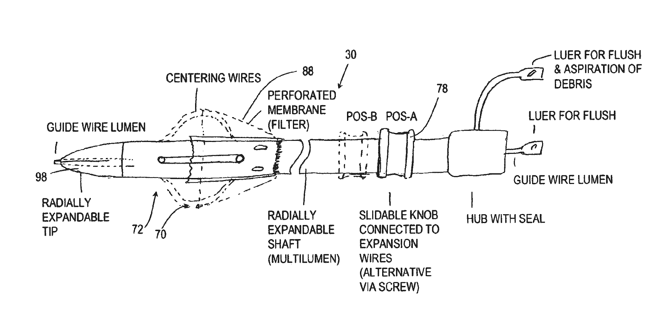
[0061]Broadly speaking, one aspect of the present invention relates to a guide catheter 30 defining a substantially tubular delivery lumen 28 through which one or more other functional catheters or devices may be introduced. In various preferred embodiments, the guide catheter 30 may have one, or any combination of two or more, of the following features (which are all optional):

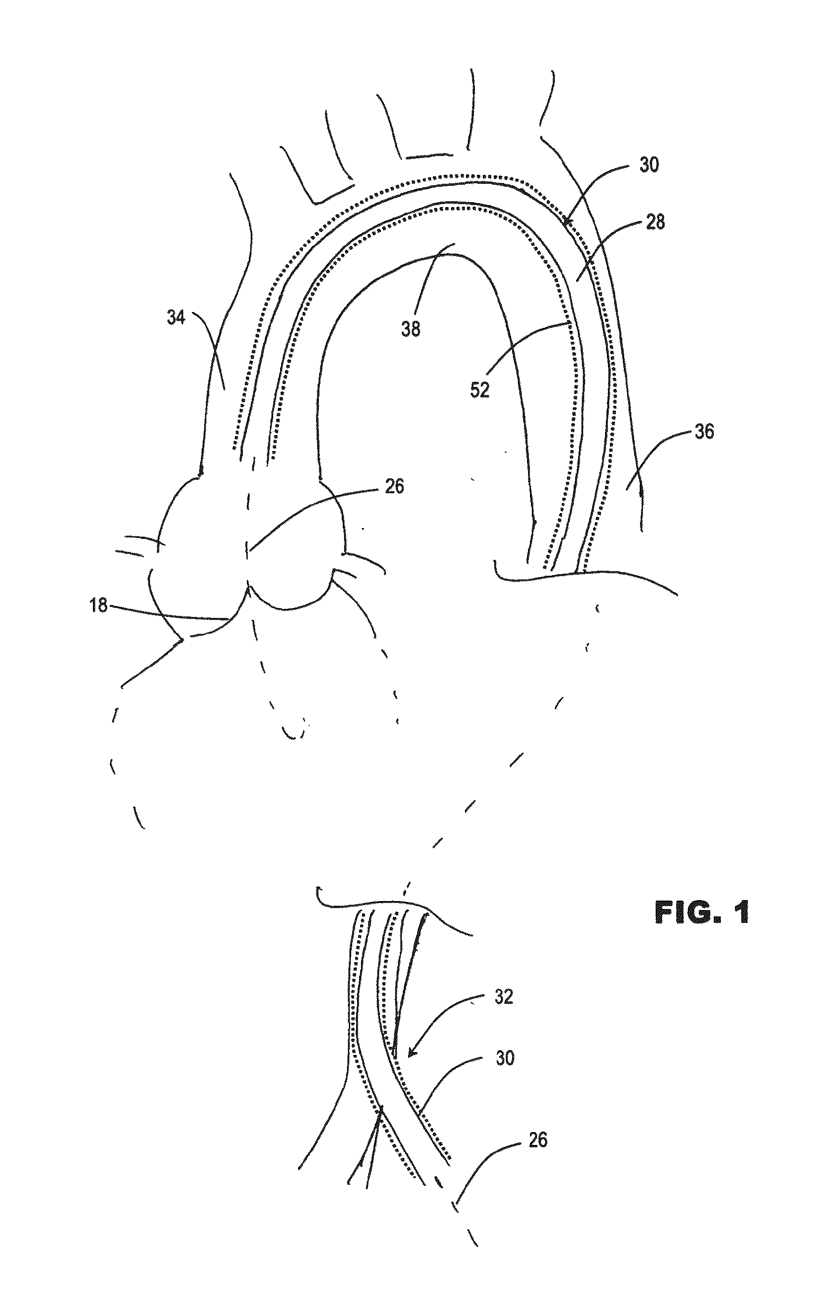
(i) Referring to FIG. 1, the guide catheter 30 may have a sufficient length to extend from a site of a skin incision 32, along a vassal route of the vasculature to a position in the ascending aorta 34. For a transfemoral approach, the guide catheter may have a sufficient length to extend from an incision 32 into the femoral artery, along the descending aorta 36, the aortic arch 38 to the ascending aorta 34. For example, a transfemoral guide catheter may have a length of at least 100 cm ...


PUM


Abstract

A guide catheter is described for introduction into a patient's vasculature, to provide a substantially continuous guide lumen within the vasculature to the ascending aorta, through which one or more other functional catheters may be introduced and removed during the procedure. The guide catheter includes an aligner at its distal region for aligning the position and / or inclination of the distal region of the guide catheter with respect to the ascending aorta. The aligner includes an embolic protection filter. The guide catheter is made of material collapsible / distensible in cross section to adopt a small shape when no catheter is present inside, and to distend to a large shape to accommodate passage of functional catheter therethrough. The cross-section shape collapses / distends by folding / unfolding of material without elastic stretching of the material.

Description

RELATED APPLICATIONS[0001]This application is a divisional of U.S. application Ser. No. 13 / 978,679, which is a national phase of PCT / EP2012 / 050303, filed 30 Sep. 2013, through which priority is also claimed to EP Application No. 11 000 150.0, filed 11 Jan. 2011, and to EP Application NO. 11 150 746.3, filed 12 Jan. 2011. The entire contents of each of these application are incorporated herein by reference.FIELD OF THE INVENTION[0002]The present invention relates to methods and apparatus useful for transcatheter aortic valve implantation (TAVI). In some non-limiting aspects, the invention is directed to implantation via a transvascular access to the heart.BACKGROUND TO THE INVENTION[0003]Traditional approaches for aortic valve replacement require the cutting of a relatively large opening in the patient's sternum (“sternotomy”) or thoracic cavity (“thoracotomy”) in order to allow the surgeon to access the patient's heart. Additionally, these approaches require arrest of the patient's ...

Claims


Application Information

Patent Timeline
Patent Type & Authority Applications(United States)
IPC IPC(8): A61F2/24A61M25/06
CPCA61F2/2436A61M25/0662A61F2310/00011A61F2210/0057A61F2310/00023A61M2025/0024A61F2310/00017A61M25/005A61M2025/1047A61F2/243A61F2/2427
Inventor DELALOYE, STEPHANEHEFTI, JEAN-LUCBIADILLAH, YOUSSEF
Owner BOSTON SCI MEDICAL DEVICE LTD
Why Eureka
Try Eureka