Composite structural member

Inactive Publication Date: 2016-07-07
LOGGO IP PTY LTD IN ITS CAPACITY AS TRUSTEE FOR THORNTON IP TRUST
View PDF27 Cites 11 Cited by
  • Summary
  • Abstract
  • Description
  • Claims
  • Application Information

AI Technical Summary

Benefits of technology

[0021]In one embodiment, the structural member is provided with a plurality of holes passing through the first, second, third, fourth (where present), fifth (where present), sixth (where present), and seventh (where present) rounds, each hole being shaped to receive one of the plurality of fasteners. In another embodiment, the plurality of holes includes holes formed at an acute angle to the longitudinal axis of the structural member and holes formed at an obtuse angle to the longitudinal axis of the structural member. In another embodiment, the f

Problems solved by technology

When trees are harvested there is significant wastage of woody material.
While these are effective uses of waste products they do not add value to the product, and merely minimise economic loss on the cost of timber production.
However, these advantages are diminished or lost where woody waste material is combusted or otherwise transformed to release carbon dioxide.
Many current uses for wood waste release significant amounts of carbon dioxide into the atmosphere, thereby exacerbating climate change and undermining the car

Method used


Image

  • Composite structural member
  • Composite structural member
  • Composite structural member

Examples


Example

Example 1

Assessment of Three Member Beam, and Comparison with Two Member Beam

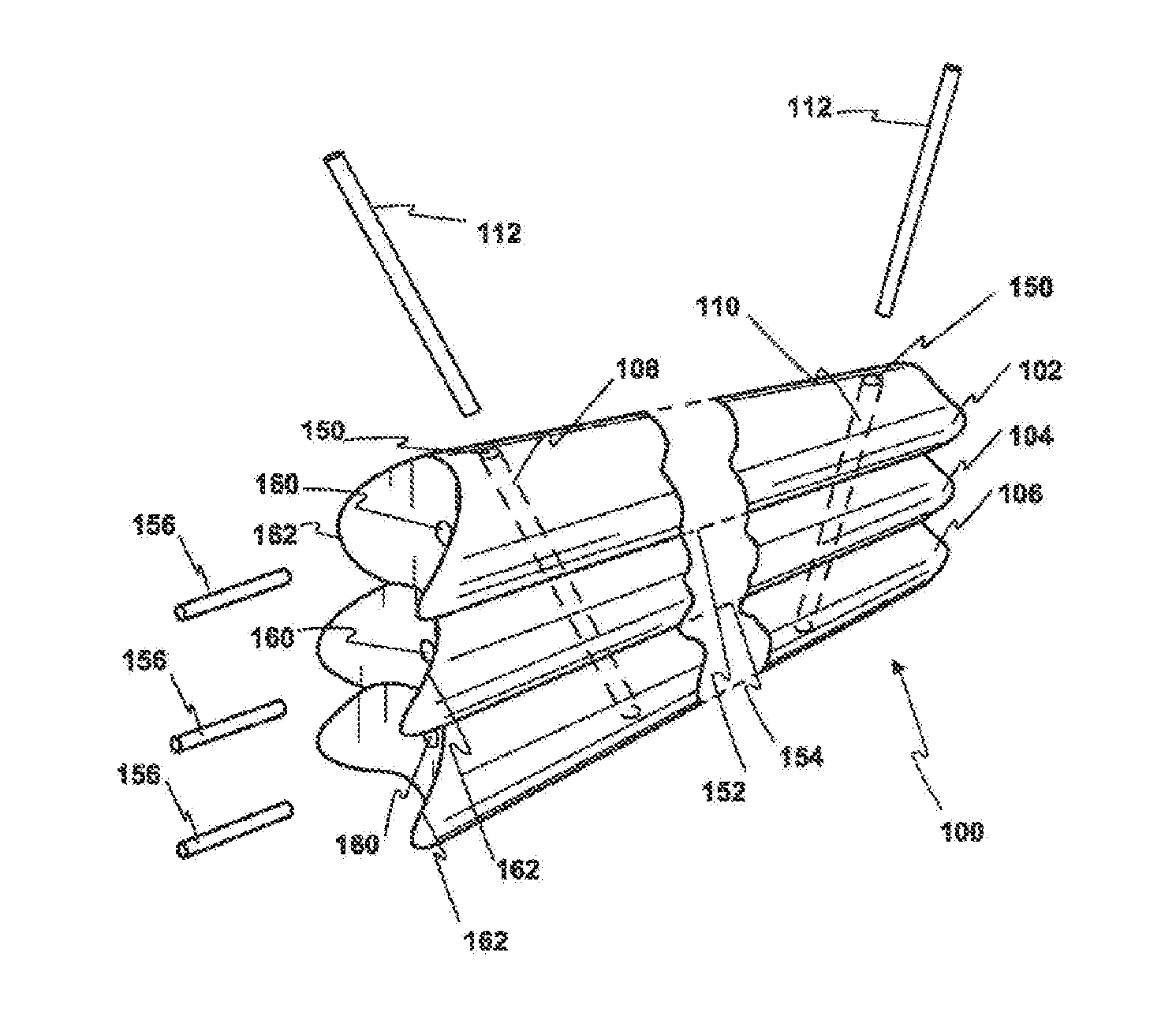
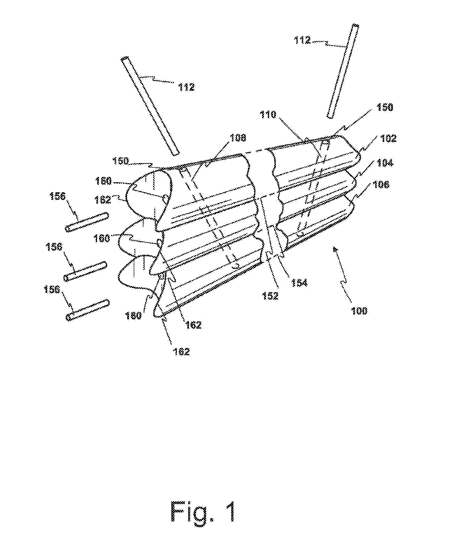
[0149]A beam produced generally in accordance with the preferred embodiment above, by using three 80 mm members. This beam was compared with a beam produced generally according to PCT / AU20091001453, by using two members of 100 mm. In both beams, fasteners were inserted alternately acutely and obtusely in a repeating V-shaped manner.

[0150]Both beams passed on strength criteria as a joist at 600 ctrs at 3.6 metre span.

[0151]Under service conditions the three member beam shows an acceptable 50% stress (F11 is 35 Mpa, and F34 is 100 Mpa).

[0152]This example demonstrates the usefulness of smaller timber rounds fabricated from wood which has previously been discarded or converted into low value products such as wood chips. Forming the smaller rounds into a three member beam using the fastening methods specified herein provides a higher value product having acceptable structural characteristics.

Example

Example 2

Cost Benefit of Three Member Beams

[0153]Applicant proposes that when using the same diameter logs with stiffness defined by reference to the moment of inertia (I=bd3 / 12), and assuming that stiffness is related to strength, and deflection is the limiting factor:

[0154]It will be noted in the above equation that b is a constant (being the width of beam), and so it is possible to compare d3 for 1, 2, 3, 4 or more members.

[0155]For example, when considering a 10 cm diameter member. (80 cm between flats): when going from a beam having 2 members (prior art) to 3 members (a beam according to the present invention) the I values will be 16 cm3 compared to 24 cm3, giving a ratio of 4096:13824. This is an advantage of almost 3.3 to 1.

[0156]In light of the above it is proposed that around 50% increase in costs provides 3.3 times the strength of the prior art two member beam.

Example

Example 3

Beam Composed of Four Members

[0157]Four peeler cores (each of only 46 mm diameter) where cut to remove a slab from opposing surfaces. The slabbed cores had a first dimension of 40 mm (taken from the first planar face formed from slabbing to the second diametrically opposite planar face), and a second dimension of 184 mm. The planar faces formed cooperating surfaces where two rounds contacted. An end-on view of the assembled composite member is shown in FIG. 4. The length of the composite member was 2200 mm.

[0158]Analysis yielded the following parameters:

Area:6306.2195 sq inPerimeter:432.8113 in.Bounding boxX: −23.0769 - 23.0709 inY: −79.9408 - 79.9408 inCentroidX: 0.0000 inY: 0.0000 inMoments of inertiaX: 13310559.5729 sq in sq inY: 880519.8341 sq in sq inProduct of inertiaXY: 0.0000 sq in sq inRadii of gyrationX: 45.9424 inPrincipal moments (sq in sq in)I: 880519.8341 along [0.0000-1.0000]and X-Y directions aboutcentroid

[0159]The preceding description details embodiments o...


PUM


Abstract

A timber structural member includes: a first timber round having a first cooperating surface, a second timber round having second and third cooperating surfaces, and a third timber round having a fourth cooperating surface. The first cooperating surface is shaped to cooperate with the second cooperating surface, and the third cooperating surface is shaped to cooperate with the fourth cooperating surface. The first, second and third timber rounds are secured together to form a structurally integral unit, wherein the first cooperating surface contacts the second cooperating surface, and the third cooperating surface contacts the fourth cooperating surface, and the first, second and third timber rounds are substantially parallel to each other. Fasteners spaced along the length of the structural member at both acute and obtuse angles from its longitudinal axis secure the first, second and third timber rounds together. The fasteners extend through the first, second and third timber rounds.

Description

FIELD OF THE INVENTION[0001]The present invention is directed to the field of construction, and in particular building construction. Included within the present invention are structural timber members capable of bearing loads required in applications such as bearers, floor joists, roof rafters, beams, columns and the like.BACKGROUND TO THE INVENTION[0002]Timber is a renewable natural resource useful in the construction of buildings and other structures. When trees are harvested there is significant wastage of woody material. Typically this material is used in relatively low value applications such as fuel for heat generation, wood chips, landscaping products, the production of bio fuels and the like. While these are effective uses of waste products they do not add value to the product, and merely minimise economic loss on the cost of timber production.[0003]Timber products act to sequester carbon dioxide for decades, thereby assisting in limiting climate change. This is a practical ...

Claims


Application Information

Patent Timeline
IPC IPC(8): E04B2/70E04B1/10E04C3/12
CPCE04B2/702E04C3/122E04B1/10E04C3/12E04C3/36E04B2/705E04C3/18
Inventor THORNTON, PATRICKBLAIR, PETER
Owner LOGGO IP PTY LTD IN ITS CAPACITY AS TRUSTEE FOR THORNTON IP TRUST
Why Eureka
Try Eureka