Cryogenic fuel compositions and dual fuel aircraft system

a technology of fuel composition and composition, applied in the field of aircraft systems, can solve the problem of low engine efficiency

Inactive Publication Date: 2016-07-07
GENERAL ELECTRIC CO
View PDF4 Cites 10 Cited by
  • Summary
  • Abstract
  • Description
  • Claims
  • Application Information

AI Technical Summary

Problems solved by technology

Use of compressor air for cooling may

Method used


Image

  • Cryogenic fuel compositions and dual fuel aircraft system
  • Cryogenic fuel compositions and dual fuel aircraft system
  • Cryogenic fuel compositions and dual fuel aircraft system

Examples


Embodiment Construction

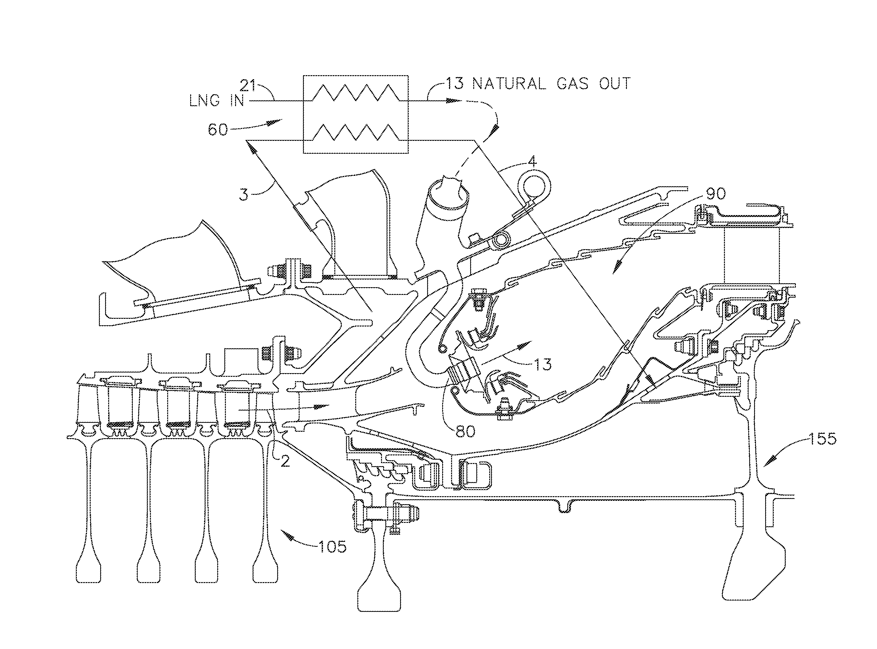
[0005]In one aspect, an embodiment of the invention relates to a cryogenic fuel composition, including liquid natural gas (LNG) and paraxylene in an amount sufficient to increase the lubricity of the composition while being soluble in LNG.

[0006]In another aspect, an embodiment of the invention relates to a cryogenic fuel composition, including a major amount of LNG and a minor amount of paraxylene having a concentration in the cryogenic fuel composition of 1 to 120 parts per million.

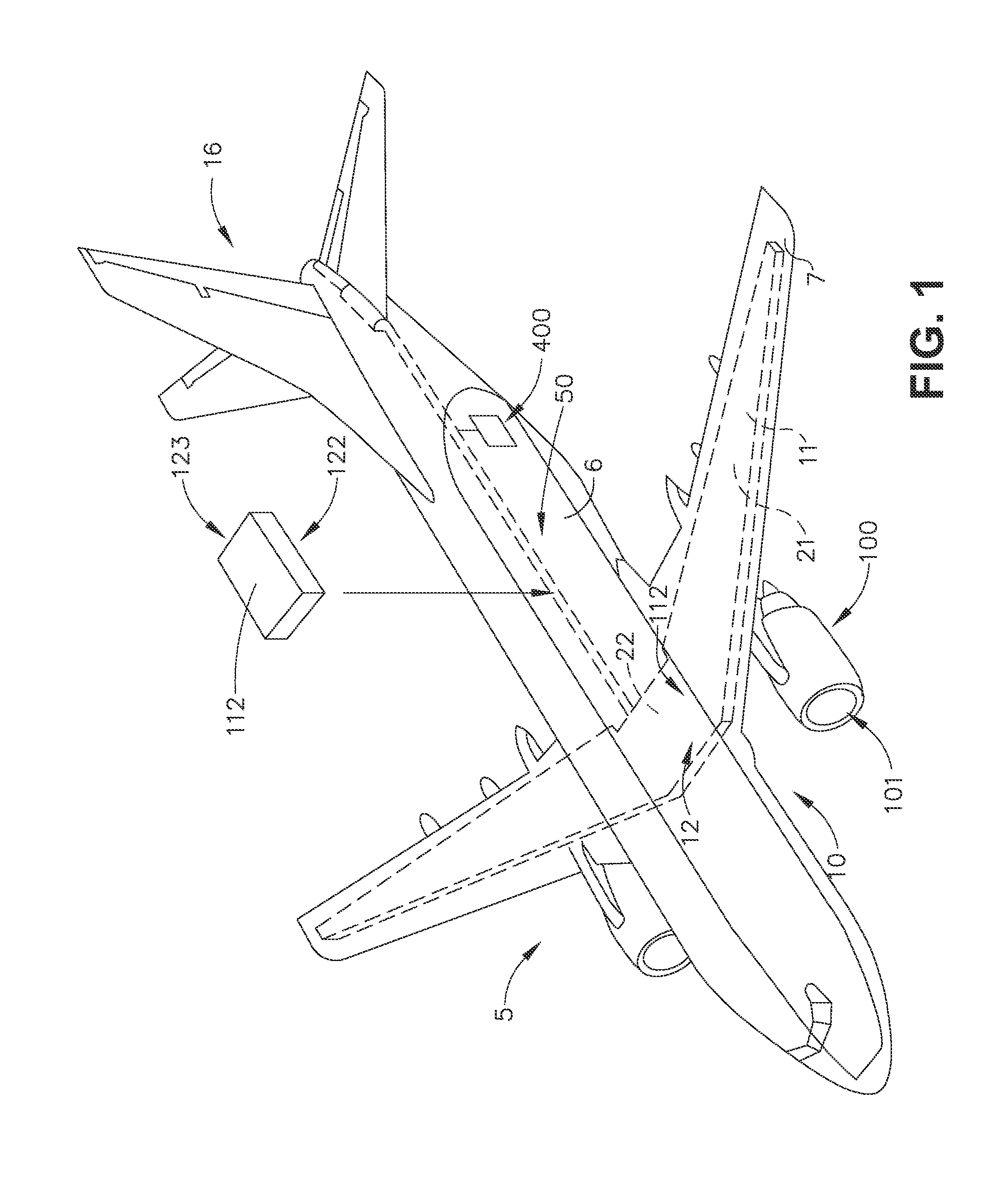
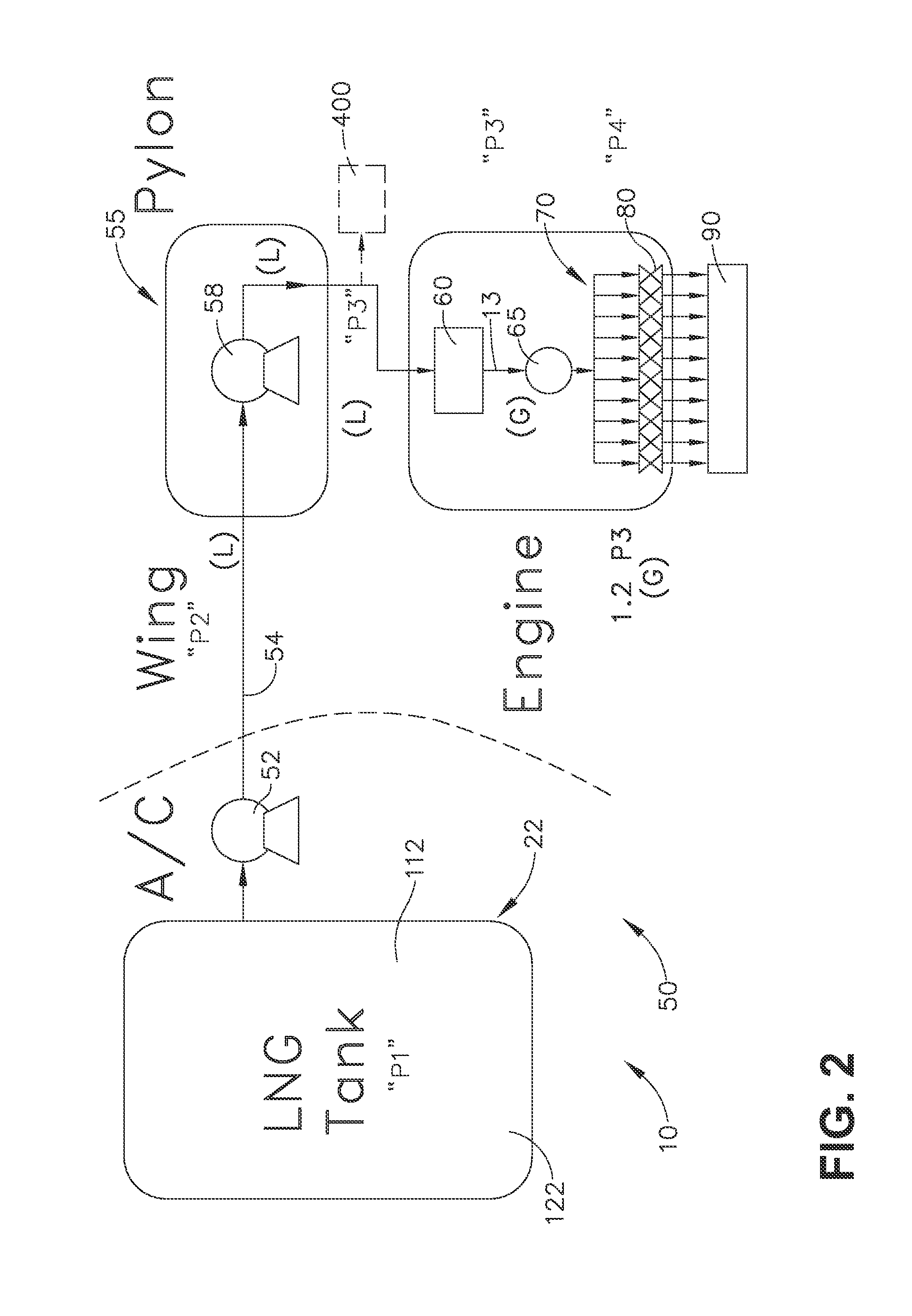
[0007]In yet another aspect, an embodiment of the invention relates to a dual fuel aircraft system for an aircraft having at least one turbine engine, having a first fuel system for providing a first fuel from a first fuel tank to the turbine engine and a second fuel system for providing a cryogenic fuel composition and having a second fuel tank storing LNG and fluidly coupled to the turbine engine, an additive tank storing additives and fluidly coupled to the turbine engine and a mixing device for confi...


PUM


Abstract

Cryogenic fuel compositions including a cryogenic fuel and paraxyelene and a dual fuel aircraft system for an aircraft having at least one turbine engine, including a first fuel system for providing a first fuel from a first fuel tank to the turbine engine and a second fuel system for providing a cryogenic fuel composition and having a second fuel tank storing LNG and fluidly coupled to the turbine engine, an additive tank storing additives and fluidly coupled to the turbine engine and a mixing device configured to create the cryogenic fuel composition.

Description

CROSS-REFERENCE TO RELATED APPLICATIONS[0001]This is a national stage application under 35 U.S.C. §371(c) of prior-filed, co-pending, PCT application serial number PCT / US2013 / 071800, filed on Nov. 26, 2013, which claims the benefit of U.S. Provisional Patent Application No. 61 / 746,900, filed on Dec. 28, 2012. These applications are incorporated herein in their entirety.BACKGROUND OF THE INVENTION[0002]The technology described herein relates generally to aircraft systems, and more specifically to aircraft systems using dual fuels in an aviation gas turbine engine and a method of operating same.[0003]Certain cryogenic fuels such as liquefied natural gas (LNG) may be cheaper than conventional jet fuels. Current approaches to cooling in conventional gas turbine applications use compressed air or conventional liquid fuel. Use of compressor air for cooling may lower efficiency of the engine system.[0004]Accordingly, it would be desirable to have aircraft systems using dual fuels in an avi...

Claims


Application Information

Patent Timeline
IPC IPC(8): F02C3/22C10L10/08F02C3/24C10L1/16
CPCF02C3/22C10L1/1608C10L2270/04F02C3/24C10L10/08C10L2290/141C10L2290/24C10L2290/02C10L3/003C10L3/08C10L2290/567F02C9/40B64D37/04B64D37/30Y02T50/40Y02T50/60Y02T90/40
Inventor EPSTEIN, MICHAEL JAYDICKEY, JENNIFER JO
Owner GENERAL ELECTRIC CO
Why Eureka
Try Eureka