Diffuser for a Forward-Swept Tangential Flow Compressor

a compressor and tangential flow technology, applied in the direction of motors, liquid fuel engines, non-positive displacement pumps, etc., can solve the problems of reducing the life of the compressor, reducing the efficiency of the centrifugal compressor, and reducing the efficiency of the compressor, so as to improve the useable static pressure rise, improve the recovery of kinetic energy, and improve the diffusion efficiency of fluid

Active Publication Date: 2016-07-07
DYNAMIC BOOSTING SYST
View PDF7 Cites 0 Cited by
  • Summary
  • Abstract
  • Description
  • Claims
  • Application Information

AI Technical Summary

Benefits of technology

[0018]The diffuser channels may be divergent only in the tangential-radial plane (a “two-dimensional diffuser”) or alternatively may diverge also in the axial-radial plane (a “three-dimensional diffuser”). Diffusion is more efficient with three dimensional diffusion channels.
[0019]Divergent diffuser channels allow for increased efficiency of diffusion of fluid from the impeller, improving the recovery of kinetic energy in the diffuser, and hence improving the useable static pressure rise. The forward sweep at the end of each diffuser channel ensures a smooth flow convergence into the collection volute, preventing blockage of the diffuser.
[0020]The diffuser may be manufactured in two injection mouldable halves, which may be split about the radial-tangential plane. Individually moulded halves allow for the divergent channels to be shaped easily in manufacturing. This is particularly so for the three-dimensional diffuser.
[0021]The diffuser channels may have a rectangular cross-section, or alternatively the walls of the channels may have chamfered or radiussed / filleted internal edges. Such edges are found to optimise fluid flow within the diffuser and to improve performance, and are particularly suitable for a compressor manufactured by injection-moulding. Surface finish is found to be important for performance, and injection-moulding is a suitable technique for producing a diffuser with an excellent finish, and with the above described desirable geometric characteristics.

Problems solved by technology

An increased shaft speed will result in increased wear and tear on bearings, reducing the life of the compressor.
Centrifugal compressors also generally exhibit low efficiency at low flow rates.
For these reasons, positive displacement compressors have been the primary method by which low flow rate applications have been managed thus far, with their disadvantages of noisy operation and high maintenance costs.
However, forward-swept compressors are known to be inherently unstable.

Method used


Image

  • Diffuser for a Forward-Swept Tangential Flow Compressor
  • Diffuser for a Forward-Swept Tangential Flow Compressor
  • Diffuser for a Forward-Swept Tangential Flow Compressor

Examples


Embodiment Construction

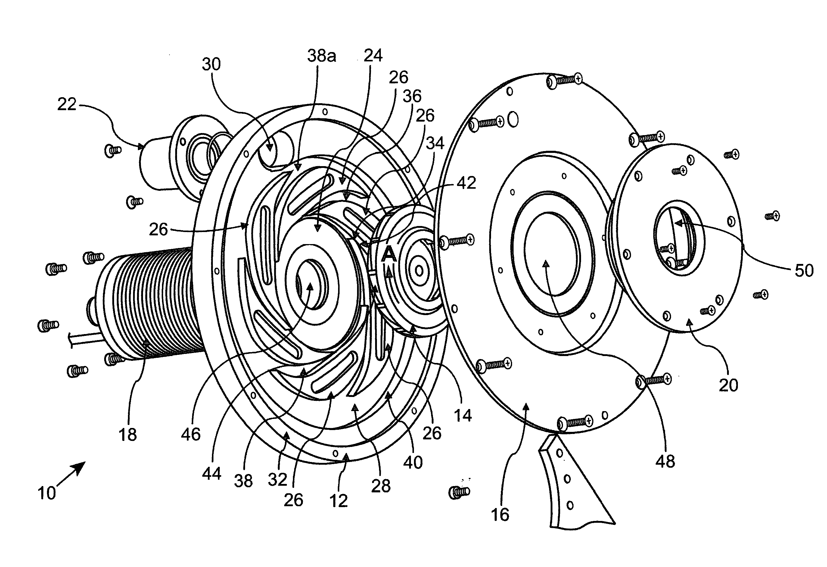
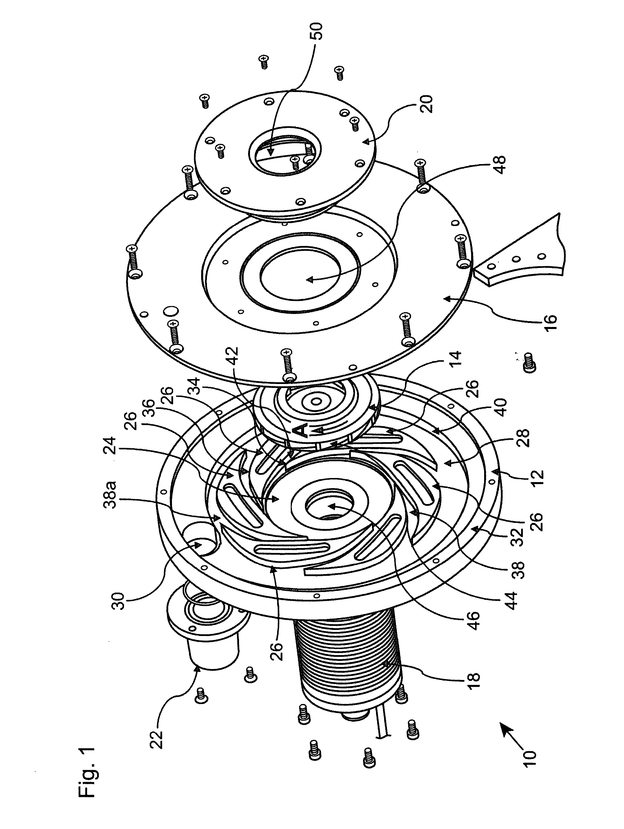
[0030]Referring firstly to FIG. 1, a centrifugal compressor is indicated generally at 10. The compressor 10 comprises a main casing 12, an impeller 14, a cover plate 16, a motor 18, a secondary cover plate 20 and an outlet assembly 22.

[0031]The main casing 12 provides a diffuser for the compressor 10, and as such includes a substantially circular space 24 for receiving the impeller 14, a plurality of diffuser vanes 26 surrounding the circular space 24, a collection volute 28 surrounding the vanes 26, and an outlet aperture 30. An outer wall 32 surrounds the collection volute and, with the cover plate 16, encloses the aforementioned parts of the diffuser.

[0032]In use, the impeller 14 sits within the circular space 24, and is driven by the motor 18 in the direction of arrow A.

[0033]The diffuser includes six vanes 26 in total, and the arrangement of vanes is rotationally symmetrical about the axis of rotation of the impeller 14. That is, each vane 26 is identical to the next, and the v...


PUM


Abstract

A diffuser for a forward-swept tangential flow compressor comprises a substantially circular space (24) for receiving a compressor impeller (14), a plurality of micro-volutes (42) adjacent to and surrounding the circular space (24), a plurality of diffuser channels (38), each diffuser channel (38) having an entrance and a discharge, and a collection volute (28), the entrance of each diffuser channel (38) extending from an associated micro-volute (42) tangentially of the circular space (24), and the collection volute (28) transitioning from the discharge of one of the diffuser channels (38), the other diffuser channels discharging into the collection volute (28), and the collection volute (28) incorporating an exit aperture (30).

Description

[0001]The present invention relates to a diffuser for a forward-swept tangential flow compressor.BACKGROUND TO THE INVENTION[0002]It is well known to provide a centrifugal compressor, which operates at high speeds, for use in the transport and energy industries.[0003]Centrifugal compressors offer advantages over positive displacement compressors, such as reciprocating compressors, rotary screw compressors, and rotary vane compressors, in that they have a much higher power density, offer oil-free compression, a low parts count and steady flow delivery.[0004]One shortcoming of centrifugal compressors when compared with positive displacement compressors is that the shaft speed must increase as the flow rate reduces. An increased shaft speed will result in increased wear and tear on bearings, reducing the life of the compressor. Centrifugal compressors also generally exhibit low efficiency at low flow rates. For these reasons, positive displacement compressors have been the primary meth...

Claims


Application Information

Patent Timeline
Patent Type & Authority Applications(United States)
IPC IPC(8): F04D29/44F04D29/42F04D17/10F04D29/28
CPCF04D29/444F04D17/10F04D29/4233F04D29/284F04D29/422F04D29/441F05D2250/52F04D29/44F04D29/30F05D2240/121F05D2240/122F05D2240/30
Inventor THORNTON, WARREN
Owner DYNAMIC BOOSTING SYST
Why Eureka
Try Eureka