
Radar apparatus for a ship

a radar and apparatus technology, applied in the field of radar apparatus for a ship, can solve the problems of conflicting technical requirements for radar apparatus, undesirable to place too much weight at a high point on a ship, and considerable losses, and achieve the effects of increasing the strength of the housing, light weight and electrical conductivity, and increasing the weight of glass fibr

Inactive Publication Date: 2016-07-07
KELVIN HUGHES
View PDF5 Cites 6 Cited by
  • Summary
  • Abstract
  • Description
  • Claims
  • Application Information

AI Technical Summary

Benefits of technology

This patent describes a radar apparatus for a ship that uses a solid state transmitter and antenna to radiate pulses of energy. The apparatus has a frusto-pyramidal shaped housing, which makes it strong, lightweight, and radar cross-section low. The use of an up-mast transmitter and / or receiver improves performance and reduces electromagnetic losses. The apparatus has a particularly low weight, with some embodiments weighing less than 100 kg. Overall, this patent provides a stealthy, lightweight, and efficient radar solution for ships.

Problems solved by technology

For reasons of stability, however, it is undesirable to place too much weight at a high point on a ship.
This leads to some conflicting technical requirements for radar apparatus.
Separation of the transmitter / receiver and antenna leads to further problems, however.
A long wave guide run requires a more powerful transmitter as there may be considerable losses through the wave guide run.
Likewise, losses in an extensive wave guide run mean that the apparatus lacks sensitivity, as received signals need to be more powerful to be detected due to losses in the wave guide run.
Further potential problems associated with long wave guide runs include the up-mast weight of the wave guide itself, and the problem that reflection and bounce of a signal along the wave guide may disadvantageously increase the minimum range of the radar apparatus.

Method used


Image

  • Radar apparatus for a ship
  • Radar apparatus for a ship
  • Radar apparatus for a ship

Examples


Embodiment Construction

[0028]Preferred embodiments of the invention will now be described with reference to figures in which

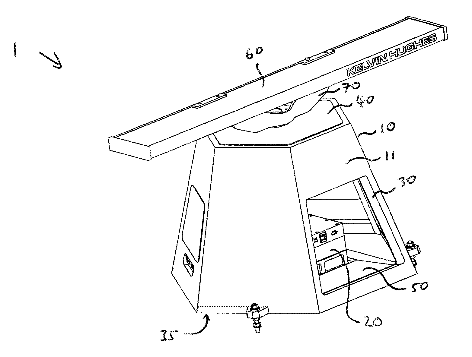
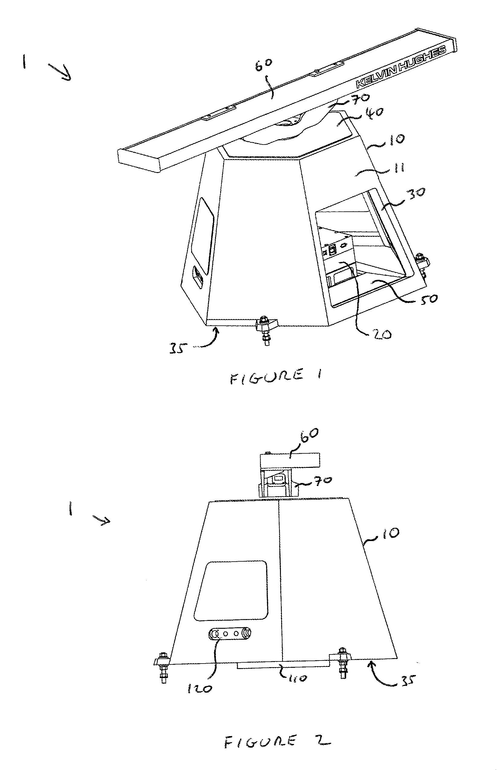
[0029]FIG. 1 shows a perspective view of a radar apparatus according to a specific embodiment of the invention;

[0030]FIG. 2 shows a side view of the radar apparatus of FIG. 1;

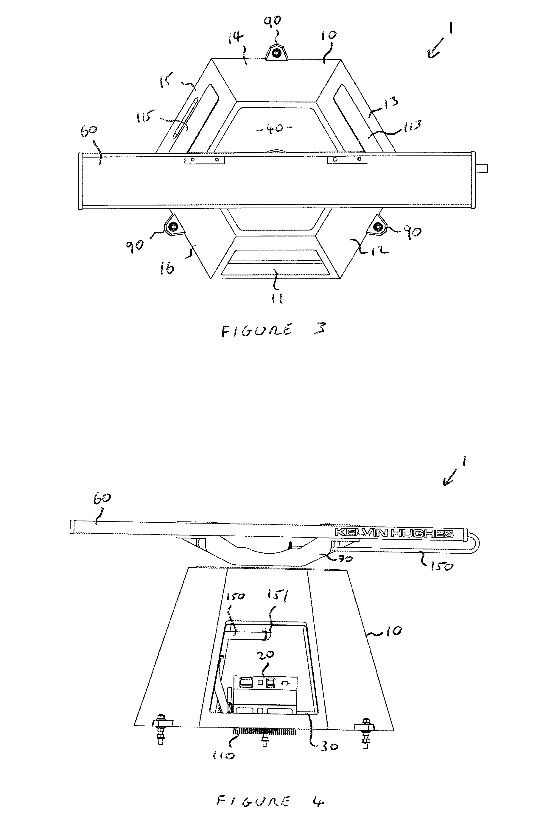
[0031]FIG. 3 shows a top plan view of the radar apparatus of FIG. 1;

[0032]FIG. 4 shows a front view of the radar apparatus of FIG. 1;

[0033]FIG. 5 illustrates a schematic cross-sectional view of a housing of the radar apparatus of FIG. 1 showing positions of a solid state transceiver and a motor within the housing;

[0034]FIG. 6 is a schematic illustration showing a solid state transceiver mounted on a heat sink extending through a portion of a housing, as may be used in the radar apparatus of FIG. 1.

[0035]FIGS. 1 to 4 illustrate a preferred embodiment of a radar apparatus 1 according to a specific embodiment of the invention. The radar apparatus 1 is a radar apparatus for a ship, and in particular a lightweight lo...


PUM


Abstract

A radar apparatus for a ship comprises a solid state transmitter and / or receiver enclosed within a housing, and an antenna coupled to the solid state transmitter and / or receiver. The external shape of the housing is substantially frusto-pyramidal. The frusto-pyramidal shape of the housing contributes to the robustness of the radar apparatus and allows the apparatus to have a low radar cross section.

Description

[0001]The invention relates to a radar apparatus for a ship comprising a solid state transmitter, or a solid state receiver, or both a solid state transmitter and a solid state receiver, enclosed within a housing shaped to provide high strength and low radar cross-section.BACKGROUND TO THE INVENTION[0002]In order to maximise the effective range of a radar system, it is preferred that radar signals are broadcast from a position that is high up on a ship, for example from the top of a mast or pole. For reasons of stability, however, it is undesirable to place too much weight at a high point on a ship. This leads to some conflicting technical requirements for radar apparatus.[0003]A radar apparatus needs to be robust and needs to withstand certain standard controlled conditions. Robustness is particularly important in the field of military radar apparatus. Thus the housing of the radar needs to be tough and of high strength in order to protect the transmitter and / or receiver, and any a...

Claims


Application Information

Patent Timeline
IPC IPC(8): H01Q1/34G01S7/28H01Q3/04G01S13/937
CPCH01Q1/34G01S2007/027G01S7/28H01Q3/04G01S13/88G01S13/937G01S7/027G01S7/032
Inventor DAVY, TERRYNORSTER, KEVINWADE, BARRY
Owner KELVIN HUGHES
Learn More