Synchronized metrology in power generation and distribution networks

Active Publication Date: 2016-07-07
DIGIMARC CORP
View PDF2 Cites 33 Cited by
  • Summary
  • Abstract
  • Description
  • Claims
  • Application Information

AI Technical Summary

Problems solved by technology

In addition to better tracking assets within the service are, there are other problems within the transmission and distribution (T&D) networks that smart meters with PhaseNet can solve.
The problem is that there is no way to automatically determine the phase that any premise is attached to.
This results in tens of millions of dollars in operating costs.
When too many premises are on different phases than the utility thinks they are on, load balancing proce

Method used


Image

  • Synchronized metrology in power generation and distribution networks
  • Synchronized metrology in power generation and distribution networks
  • Synchronized metrology in power generation and distribution networks

Examples


Embodiment Construction

[0022]Onboard a typical smart meter are two primary circuit boards: 1) a metrology board; and 2) a communications board. These communications boards each have their own clock and / or oscillators that can provide count-stamps, which are the raw timing and location information for the PhaseNet algorithms.

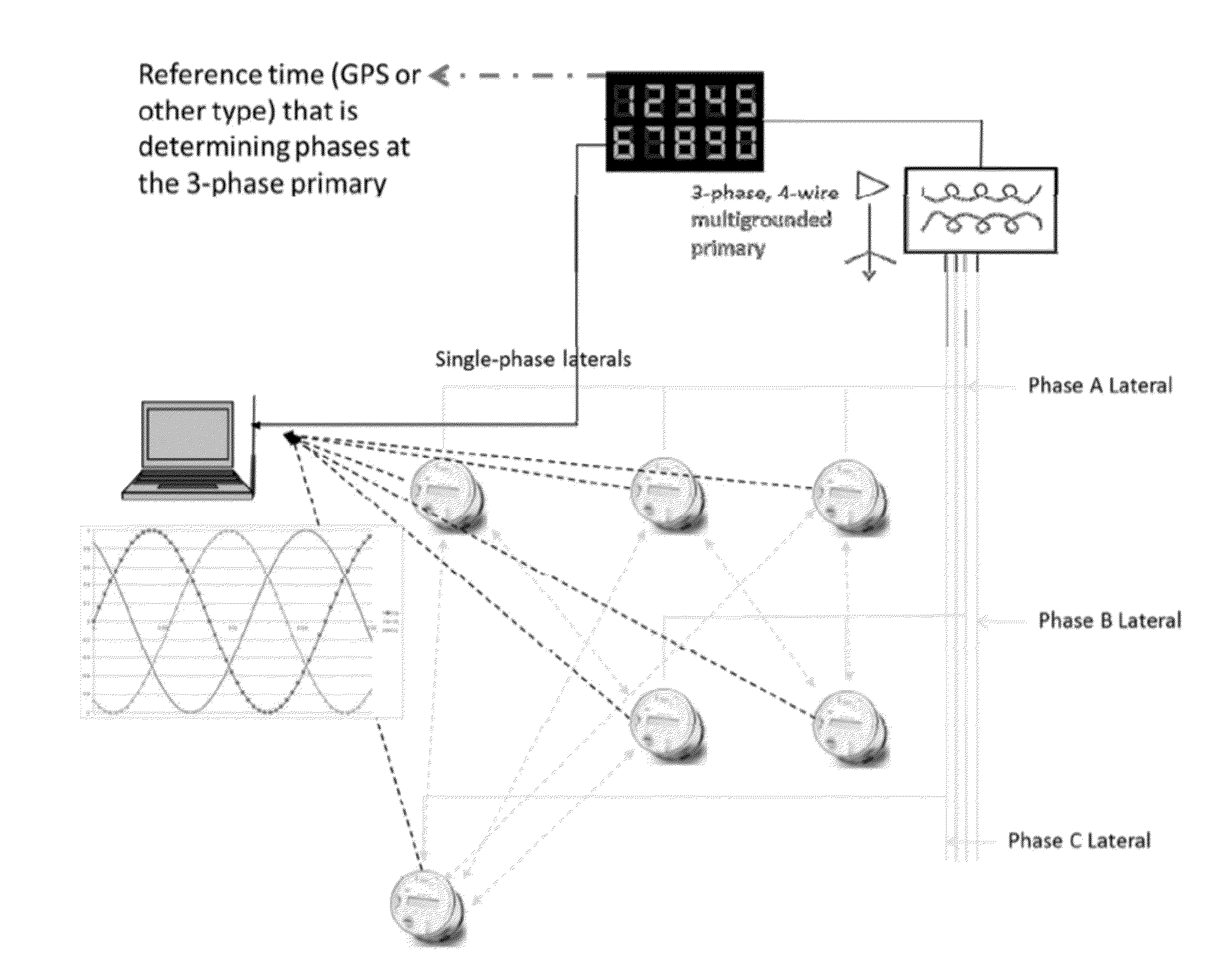
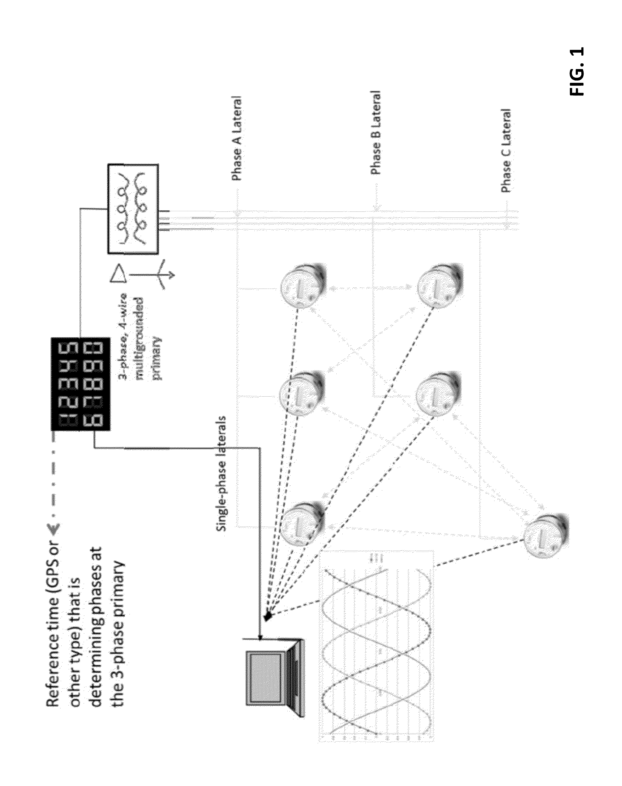
[0023]In implementation, a network communication script is implemented, for example, from a sub-station. The script looks very similar to the normal ‘meter reading’ scheduling already happening that routes usage data about the premises to the utility. For example, Sub-station A exchanges several duplex packets with meters B, C and D over a few tens of seconds of time; Meter B duplex exchanges several packets with E, F and G before, during, or after the A exchanges; Meter G duplex exchanges with H and I, same drill, before, during or after. This is consistent with the space-time network description embodied in previous filings by the applicant, mainly U.S. Pat. No. 7,876,266.

[0024]At ea...


PUM


Abstract

Phasor Measurement Units (PMUs) tend to be specialized and expensive—relegated to only key points in power distribution networks, and are generally reliant on GPS technology. The present disclosure details how any smart meter—using wireless communication—can perform sub-microsecond-grade synchrophasor measurements. Other aspects concern smart meter-based determination of A, B or C phase of the tri-phase power network. This can involve count-stamp enabling message packets sent to and/or from a smart meter, and then associating such count-stamps to local measurements of power phase by a metrology unit. Once a network of such enabled smart meters and other devices is formed, sub-microsecond metropolitan-wide and entire region-wide synchronizing time standard can calibrate local measurements of power phase, where simple A, B and C phase determination is one low hanging fruit application of such. Low cost aggregate monitoring of metropolitan-wide synchrophasors promises a next chapter of importance for that relatively recent art.

Description

RELATED APPLICATION DATA[0001]This application is a continuation in part of application Ser. No. 14 / 220,838, filed Mar. 20, 2014, which claims the benefit of provisional 61 / 803,540, filed Mar. 20, 2013, and which also is a continuation in part of application Ser. No. 13 / 765,404, filed Feb. 12, 2013 (now U.S. Pat. No. 9,230,429). Application Ser. No. 13 / 765,404 claims priority benefit to provisional applications 61 / 727,050, filed Nov. 15, 2012, and 61 / 727,293, filed Nov. 16, 2012. Application Ser. No. 13 / 765,404 also is a continuation-in-part of PCT application PCT / US 12 / 50994, filed Aug. 15, 2012, which claims priority benefit to provisional application 61 / 575,178, filed Aug. 15, 2011.[0002]Priority is claimed to each of the above applications. Each of the above applications is incorporated herein by reference.TECHNICAL FIELD[0003]The present technology concerns smart grid systems, such as for electric power metering.INTRODUCTION TO THE TECHNOLOGY[0004]“Smart Grid” technologies offe...

Claims


Application Information

Patent Timeline
IPC IPC(8): H04Q9/00G01R29/18G01R19/25G01D4/00G01R19/175
CPCH04Q9/00G01D4/002H04Q2209/60G01R19/2513G01R29/18G01R19/175G01R22/10G06Q50/06G08C19/12H04Q9/04Y02B90/20Y02E60/00Y04S10/00Y04S20/30Y04S10/22Y02E40/70G01D2204/45G01D2204/47
Inventor RHOADS, GEOFFREY B.EUSTIS, CONRADMCKINLEY, TYLER J.
Owner DIGIMARC CORP
Why Eureka
Try Eureka