Concrete mixer with perfected auxiliary device

a technology of auxiliary devices and concrete mixers, applied in cement mixing apparatuses, concrete transportation, vehicle sub-unit features, etc., can solve the problems of reducing operating flexibility, reducing functioning autonomy, and one or both having to be kept working

Active Publication Date: 2016-07-14
CIFA
View PDF3 Cites 13 Cited by
  • Summary
  • Abstract
  • Description
  • Claims
  • Application Information

AI Technical Summary

Benefits of technology

[0040]In this way it is possible to identify a second kinematic-energy chain that comprises the reversible kinetic / mechanical energy recovery device and the at least one accumulator. The second kinematic energy chain can be disconnected from the heat engine of the vehicle and can supply, in the same way as described above, mechanical energy both to the drum and to the vehicle itself, taking it from the accumulator.

Problems solved by technology

One considerable disadvantage of known concrete mixer trucks is that the heat engine, whether it is the only one which moves the vehicle, or whether it is both the above cited heat engines, in the place where the concrete mixer truck is loaded and at the building site, one or both must be kept functioning, both to move the mixer truck and to rotate the drum.
It is also known that heavy vehicles, such as concrete mixer trucks, as well as being a source of noise also emit noxious gases from the heat engines.
This solution is limited, however, in that it has a reduced operating flexibility due mainly to the univocal power, entrusted each time only to the generator or only to the accumulation batteries, with a subsequent reduction in functioning autonomy.
Another disadvantage faced is to provide an almost total reduction of the noise produced by the concrete mixer trucks during their own movement, on the road or in the areas of work.

Method used


Image

  • Concrete mixer with perfected auxiliary device
  • Concrete mixer with perfected auxiliary device
  • Concrete mixer with perfected auxiliary device

Examples


Embodiment Construction

[0046]The present invention complements and perfects the invention of MI2012A000093 (MI'093).

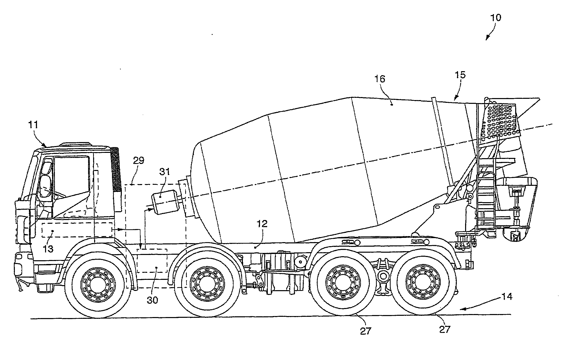
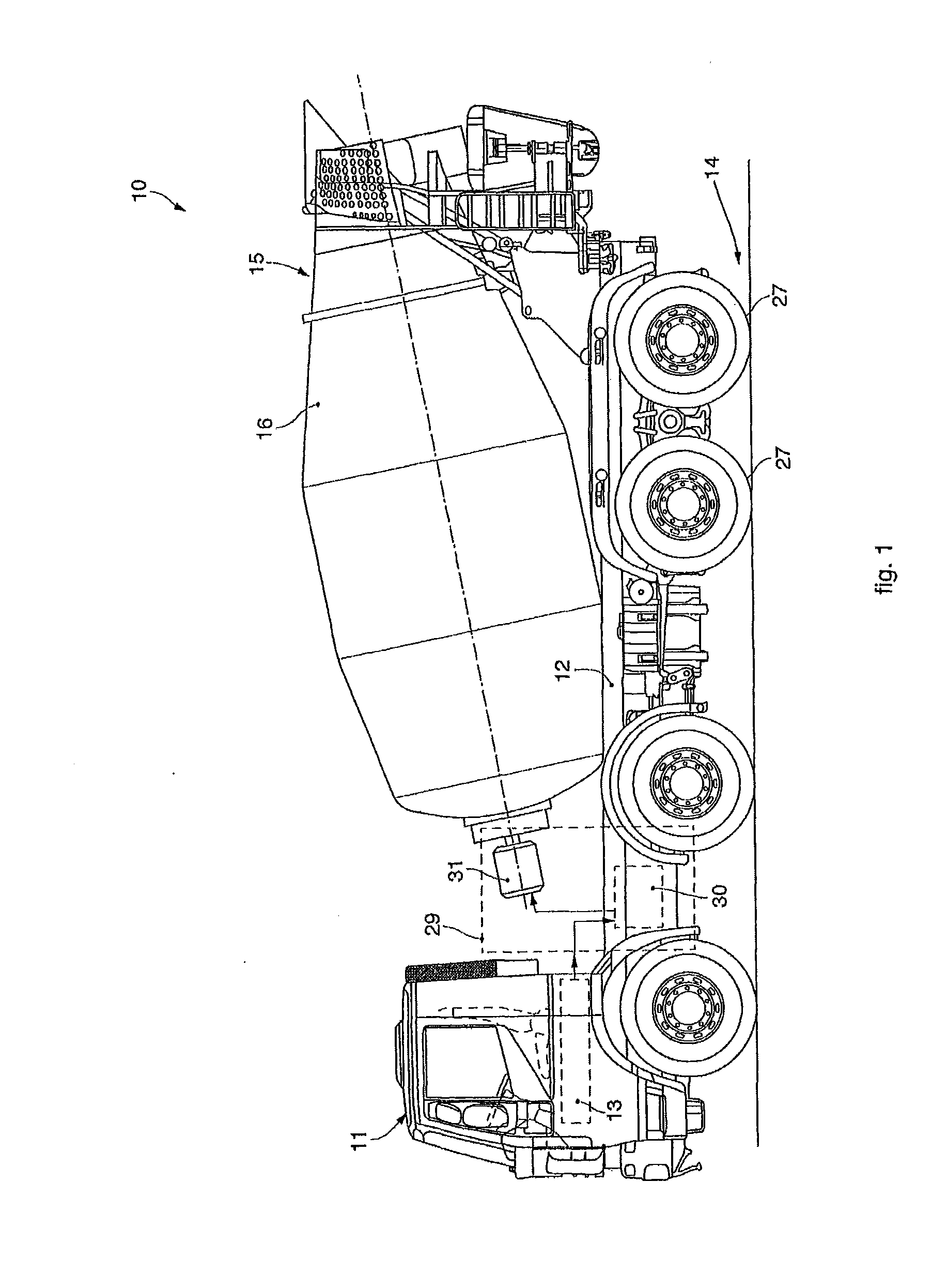
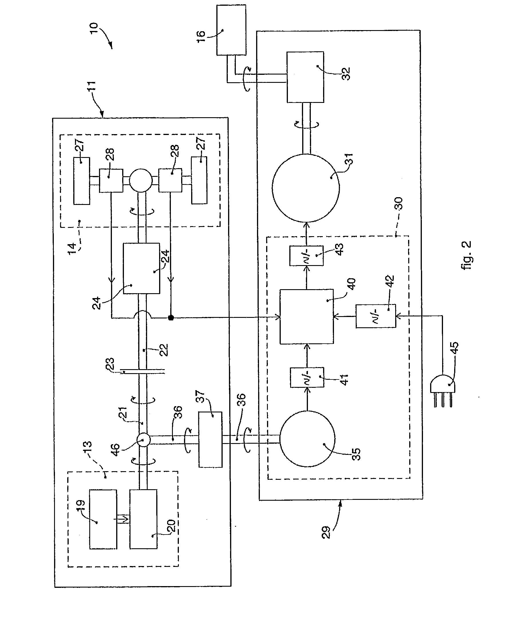
[0047]FIGS. 1 and 2 show the inventive idea proposed in said application and therefore part of the state of the art which the present invention intends to perfect. In particular, FIG. 1 shows a schematic lateral view of a concrete mixer truck, while FIG. 2 schematically shows the concrete mixer truck according to the inventive idea of application MI'093.

[0048]For the purposes of clarity and completeness of the description, in the present application the same reference numbers are maintained as in application MI'093, which is incorporated entirely herewith by way of reference.

[0049]With reference to FIG. 1, a concrete mixer truck 10 comprises a vehicle 11, for example a truck, of any known type, provided with a frame 12 on which a rotating drum 16 of a concrete mixer 15 is mounted. For example the capacity of the drum 16 is comprised between 4 cubic meters and 12 cubic meters.

[0050]The vehicl...


PUM

PropertyMeasurementUnit
poweraaaaaaaaaa
poweraaaaaaaaaa
poweraaaaaaaaaa

Abstract

A concrete mixer truck comprises a vehicle provided with a heat engine and a concrete mixer having a rotating drum and an auxiliary device provided with a unit for generating electric energy that selectively feeds an electric motor connected to the rotating drum. The electric energy generating unit comprises at least an alternator selectively connectable to the heat engine and to a movement unit of the vehicle by means of a gearbox and a power take-off positioned between the clutch of the vehicle and the gearbox. The alternator is configured to convert mechanical energy into alternate electric energy and vice versa. The electric energy generating unit also comprises at least one accumulator and reversible conversion means of electric energy, connected to the accumulator and to the alternator in order to selectively take continuous electric energy from the former and supply alternate electric energy to the latter, to move the drive wheels of said movement unit, or to convert the alternate electric energy produced by the alternator into continuous electric energy to be transferred to the accumulator.

Description

FIELD OF THE INVENTION[0001]The present invention concerns a concrete mixer truck which has an auxiliary device, suitable when activated both to move the mixer truck, in determinate circumstances, and also to make the drum rotate in order to mix the concrete.[0002]In particular, the auxiliary device uses the mechanical energy of the heat engine normally used in concrete mixer trucks to make available a quantity of energy which can be exploited both to move the vehicle that acts as a means of transport for the mixing drum, and also to make the drum itself rotate.BACKGROUND OF THE INVENTION[0003]The use of concrete mixer trucks is known, which using a rotating drum transport concrete from a production plant to the building site where the concrete is used.[0004]Both during the loading step in the production plant, and during the transport step to the building site, the concrete has to be kept malleable, and so the rotating drum has to be kept in constant rotation so that the concrete d...

Claims


Application Information

Patent Timeline
Patent Type & Authority Applications(United States)
IPC IPC(8): B28C5/42B60K25/00B60P3/16
CPCB28C5/421B60K25/00B60P3/16B60K6/48B60K25/06B60Y2400/214Y02T10/62
Inventor PIRRI, NICOLAZORZI, EMANUELECHELI, FEDERICOMAPELLI, FERDINANDOTARSITANO, DAVIDE
Owner CIFA
Why Eureka
Try Eureka