Shaft Sounding Device for Measuring Thickness of Sediments at Base of Drilled Shafts

a sounding device and drilling shaft technology, applied in the direction of instruments, borehole/well accessories, surveys, etc., can solve the problems of requiring specialized trained personnel, affecting the efficiency and effectiveness of assessing shaft bottom cleanliness, and requiring expensive equipment, etc., to achieve simple, reliable and quantitative results, and improve cost effectiveness

Inactive Publication Date: 2016-07-14
FUNG STEVE WILHELM
View PDF10 Cites 11 Cited by
  • Summary
  • Abstract
  • Description
  • Claims
  • Application Information

AI Technical Summary

Benefits of technology

[0015]The embodiments of the invention will improve the state of the current practice. It will measure the sediment thickness at the base of drilled shafts using sounding methods by providing a simple, reliable and quantitative means of measuring the sediment thickness. The invention measures the sediment thickness by using the mass of a weighted piston to push a probe shaft into the sediments, and uses a bearing plate and measuring ring centered around the axis of the probe shaft to measure the distance the probe point penetrates the sediments.
[0016]Another embodiment of the invention is to provide a lightweight and portable system for measuring the thickness of the sediment at the base of drilled shafts. The invention is designed to be less than 5 pounds in weight and can be transported, setup, and used by a single operator.
[0017]Yet another embodiment of the invention is to provide a reliable system for measuring the thickness of sediments at the base of drilled shafts—where the measurements obtained by the invention are not subject to interpretation and can be duplicated by different operators using the same device.
[0018]Other embodiments of the invention also include: the invention is designed to be simple enough to be operated by construction and engineering personnel. It is designed to check shaft bottom cleanliness without the operator entering into the drilled shaft. It is also designed to be more cost effective than visual inspection devices by having a lower cost; less complex to operate, and takes little time to perform the test to determine the sediment thickness at the base of the drilled shafts.
[0019]The advantages of the invention include, without limitation: lightweight; low cost; provides quantitative measurements; portable; easy to transport; easy to operate; and measurements can be performed quickly and duplicated.

Problems solved by technology

These methods currently have limitations to the efficiency and effectiveness of assessing shaft bottom cleanliness, such as:
Downhole inspection by personnel lowered to the excavated drilled shaft bottom is typically avoided due to safety concerns and cannot practically be performed in wet drilled shafts.
Visual inspection using video / camera devices is relatively time consuming, uses expensive equipment and requires specialized trained personnel.
This can potentially lead to drilled shaft settlement and disputes.

Method used


Image

  • Shaft Sounding Device for Measuring Thickness of Sediments at Base of Drilled Shafts
  • Shaft Sounding Device for Measuring Thickness of Sediments at Base of Drilled Shafts
  • Shaft Sounding Device for Measuring Thickness of Sediments at Base of Drilled Shafts

Examples


Embodiment Construction

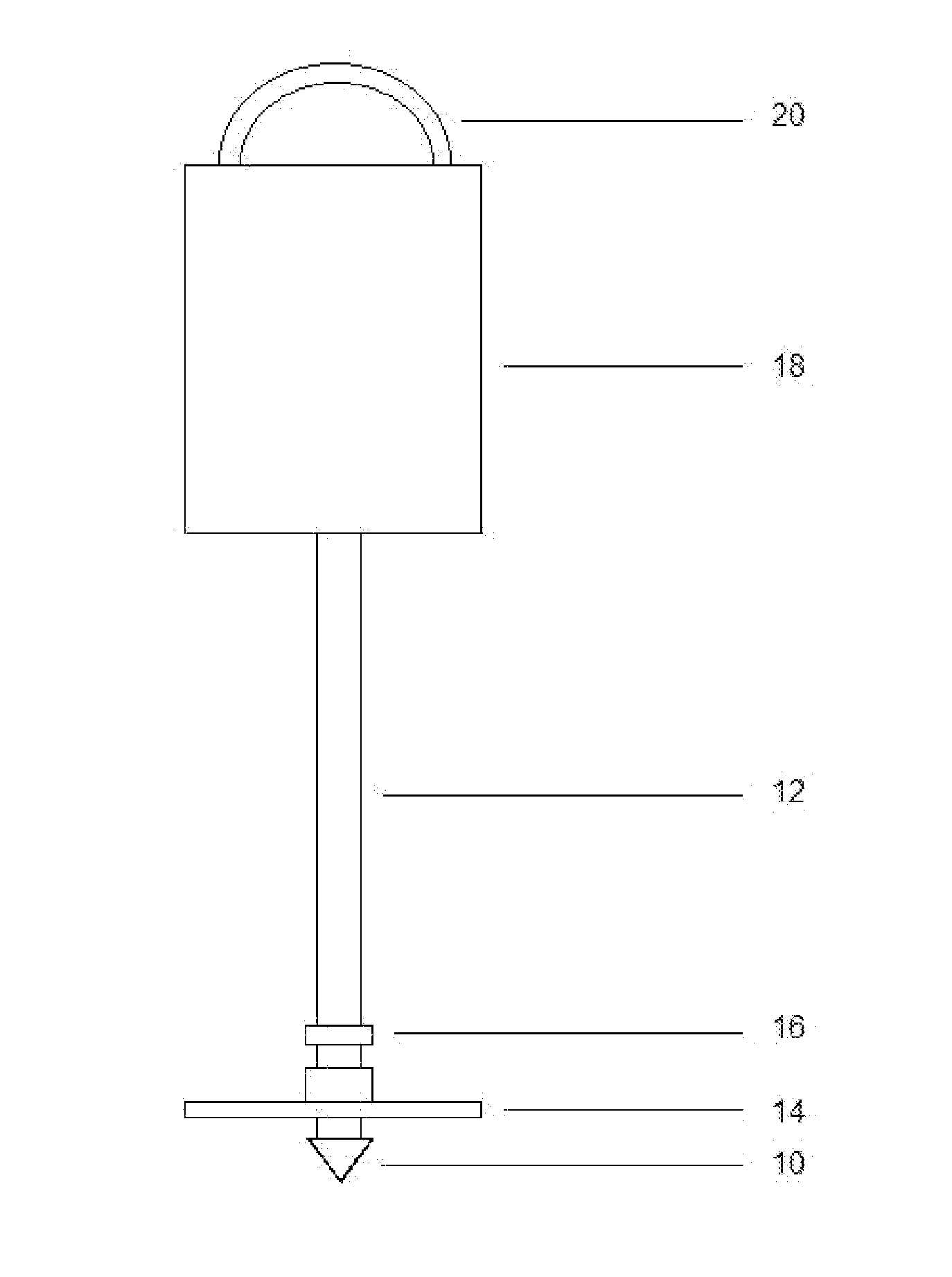
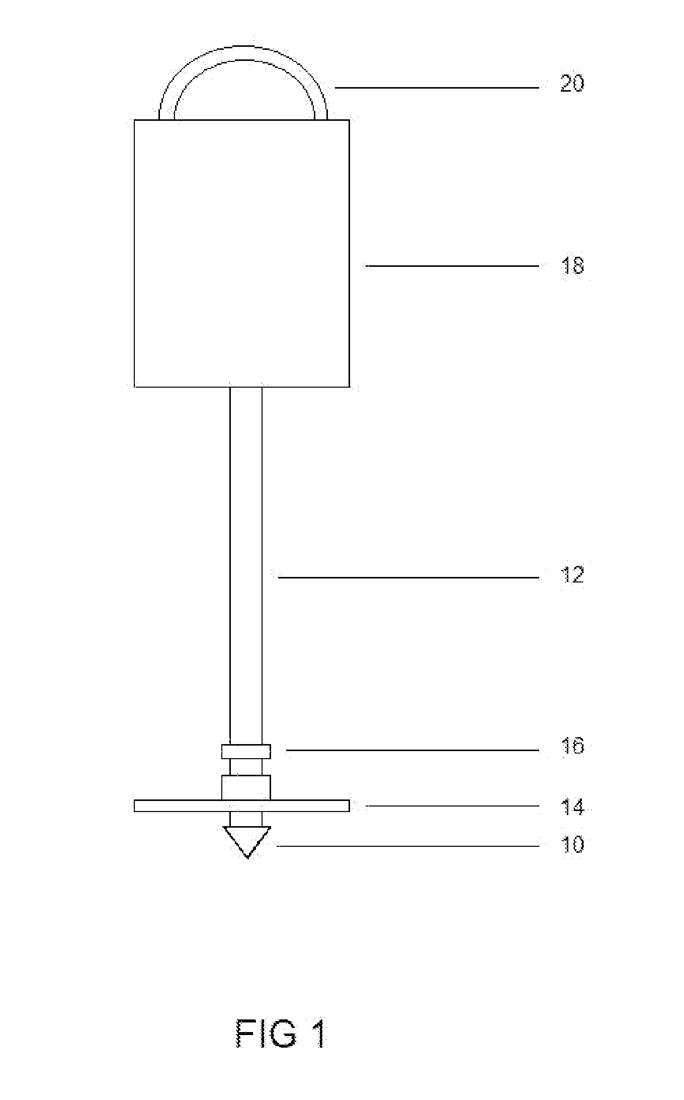
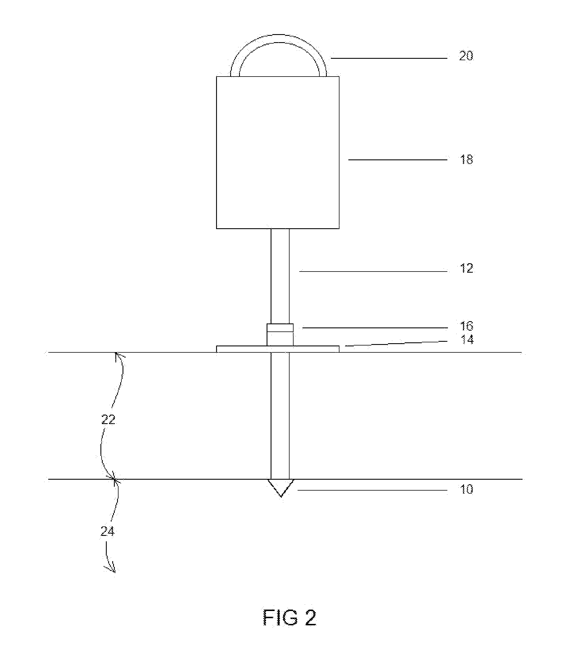
[0024]The invention consists of a sounding device that is designed to measure the thickness of sediments at the base of drilled shaft excavations. The system and features of the sounding device are described in the following paragraphs and the references are on the appended drawings:

[0025]FIG. 1 shows the concept of the sounding device. The sounding device includes the following elements:

[0026]The probe point 10 is conical (pointed) in shape.

[0027]The probe shaft 12 will have a measurement scale annotated on it. The measurement scale will be in either inches or millimeters. The graduated length of the probe shaft 12 will be a minimum of 2 inches. Probe shafts 12 with longer lengths will be used if the thickness of the sediment 22 is expected to exceed 2 inches.

[0028]The bearing plate 14 size (diameter) will vary from 1 to 3 inches in diameter and will be mounted on a sleeve to allow free movement along the probe shaft 12 and to prevent tilt of the bearing plate 14. Selection of the ...


PUM

PropertyMeasurementUnit
weightaaaaaaaaaa
thicknessaaaaaaaaaa
weightaaaaaaaaaa

Abstract

A sounding device for measuring the thickness of sediments at the base of dry or wet drilled shaft excavations for the assessment of drilled shaft bottom cleaning operations. The sounding device provides a simple and reliable means to quantitatively evaluate drilled shaft bottom cleanliness.

Description

CROSS REFERENCES TO RELATED APPLICATIONS[0001]Not ApplicableSTATEMENT REGARDING FEDERALLY SPONSORED RESEARCH OR DEVELOPMENT[0002]Not ApplicableBACKGROUND OF THE INVENTION[0003]This invention relates to the assessment of drilled shaft bottom cleaning operations. The invention provides a simple, reliable and quantitative means of measuring the thickness of sediments when accessing drilled shaft base cleanliness.[0004]Drilled shafts are high capacity deep foundation bored piles that are constructed by excavating a hole in the ground and placing fluid concrete within the excavation. Drilled shafts have several advantages over other types of deep foundations, and one of its advantages is the ability to resist high axial loads. The axial load resistance of a drilled shaft is derived for the side resistance of the concreted shafts in the surrounding soils or rock, and from end bearing resistance of the poured concrete on soil or rock. Therefore, the cleanliness of drilled shaft bases is im...

Claims


Application Information

Patent Timeline
Patent Type & Authority Applications(United States)
IPC IPC(8): G01B21/08G01N33/24
CPCG01N33/24G01B21/08
Inventor FUNG, STEVE WILHELM
Owner FUNG STEVE WILHELM
Why Eureka
Try Eureka