Inductive Power Transfer System

a technology of inductive power transfer and inductive power, applied in the direction of transportation and packaging, efficient power electronics conversion, climate sustainability, etc., can solve the problems of occupying useful volume, requiring heavy materials, and employing expensive fabrication techniques

Inactive Publication Date: 2016-07-14
FREEVOLT TECH LTD
View PDF4 Cites 12 Cited by
  • Summary
  • Abstract
  • Description
  • Claims
  • Application Information

AI Technical Summary

Problems solved by technology

Field-shaping techniques normally occupy useful volume, require heavy materials, employ expensive fabrication techniques and need a precise coil alignment.
These solutions make the field-shaping approach unsuitable for many applications, where the size, weight and cost of the system are limiting factors.
In the past, this approach was not considered efficient, since low driver efficiency (due to semiconductor losses) dramatically reduced the end-to-end efficiency of the IPT system.

Method used


Image

  • Inductive Power Transfer System
  • Inductive Power Transfer System
  • Inductive Power Transfer System

Examples


Embodiment Construction

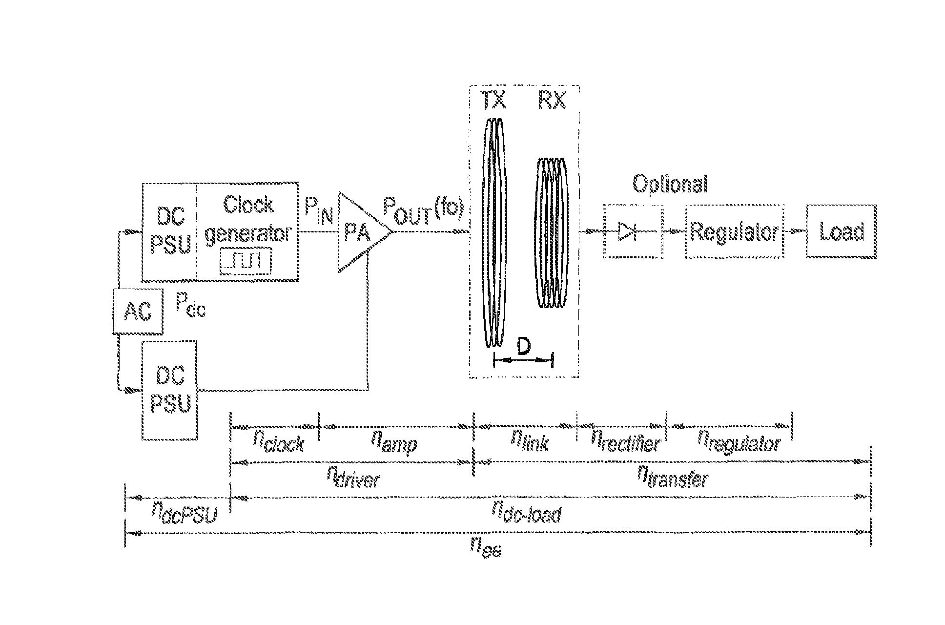
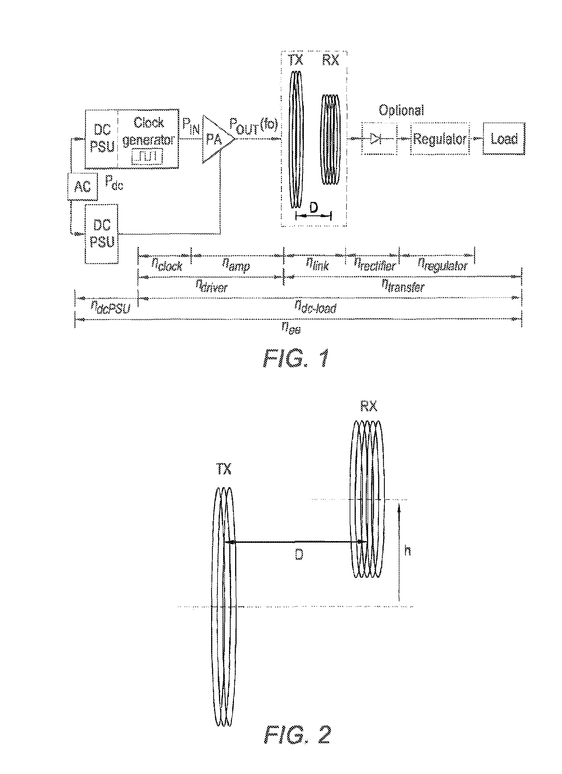
[0059]Inductive Power Transfer (IPT) systems for transmitting tens to hundreds of watts have been reported for almost a decade. Most of the work has concentrated on the optimization of the link efficiency and has not taken into account the efficiency of the driver. Class-E amplifiers have been identified as ideal drivers for IPT applications, but their power handling capability at tens of MHz has been a crucial limiting factor, since the load and inductor characteristics are set by the requirements of the resonant inductive system. The frequency limitation of the driver restricts the unloaded Q factor of the coils and thus the link efficiency. With a suitable driver, copper coil unloaded Q factors of over 1,000 can be achieved in the low MHz region, enabling a cost-effective high Q coil assembly. The system described herein alleviates the use of heavy and expensive field-shaping techniques by presenting an efficient IPT system capable of transmitting energy with a dc-to-load efficie...


PUM


Abstract

The invention relates to an inductive power transfer transmitter comprising class-E amplifier driver arranged to drive a primary tank circuit including a transmitter coil, in which the driver frequency is tuned to drive the primary tank circuit when the primary tank circuit is in an unloaded condition.

Description

[0001]This invention relates to an inductive power transfer system. In general terms this application relates to maximising DC to load efficiency for inductive power transfer.BACKGROUND[0002]Inductive power transfer (IPT) without a magnetic core was first proposed by Nikola Tesla to supply wireless mains power over long distances around 100 years ago [1]. Since then, low-power, closely-coupled wireless charging methods have been used to power medical implants [2], while the wireless powering of portable devices through charging mats is now available via commercial products [3]. Nonetheless, there has been recent interest in wireless power transfer (WPT) for medium range (i.e. 10 s of cm) applications, such as electric vehicle charging through resonant inductive coupling [4]-[7].[0003]For many industrial and commercial applications, IPT systems must be capable of achieving a high end-to-end efficiency gee, while transferring hundreds of watts at submetre distances, otherwise they wil...

Claims


Application Information

Patent Timeline
Patent Type & Authority Applications(United States)
IPC IPC(8): H02J7/02
CPCH02J7/025H02M7/537H02J50/12H02J50/90Y02B70/10H02J50/70H02M7/4815
Inventor MITCHESON, PAUL DAVIDLAWSON, JAMESRANGEL, MANUEL PINUELAYATES, DAVID CHRISTOPHER
Owner FREEVOLT TECH LTD
Why Eureka
Try Eureka