Non-barrier chambered pressurized reservoir

a pressure reservoir and chamber technology, applied in the field of pressure vessels, can solve the problems of additional cost, lack of means, and constraints on packaging, and achieve the effect of less dead hydraulic fluid

Inactive Publication Date: 2016-07-21
PARKER HANNIFIN CORP
View PDF11 Cites 2 Cited by
  • Summary
  • Abstract
  • Description
  • Claims
  • Application Information

AI Technical Summary

Benefits of technology

[0006]The present invention provides a pressurized vessel that uses a gas-fluid boundary for enabling trapped gas to naturally escape the hydraulic working fluid, but which can be mounted horizontally for efficient packaging, and / or that uses less dead volume of hydraulic fluid while preventing the gas-fluid boundary from reaching the outlet of the reservoir.

Problems solved by technology

A problem with these typical non-barrier reservoirs is that the gas-fluid boundary can shift in the reservoir, for example when used on a vehicle that accelerates or changes slope, which may cause the gas-fluid boundary to reach the reservoir outlet, allowing gas to reenter the hydraulic system.
A disadvantage of typical non-barrier reservoirs includes packaging constraints due to their vertical orientation, as well as the additional cost associated with transporting an otherwise unnecessary dead volume of hydraulic fluid.
In contrast to the above-referenced non-barrier-type reservoir, the barrier-type reservoir does not provide a head space for allowing trapped gas to escape from the hydraulic system, and therefore does not have a gas-fluid boundary where the gas and hydraulic fluid interact.
However, a disadvantage of the barrier-type reservoir is that it does not provide a means for trapped gases to naturally escape from the working fluid through a gas-fluid boundary, and therefore requires a separate degassing system for removal of the trapped gas.

Method used


Image

  • Non-barrier chambered pressurized reservoir
  • Non-barrier chambered pressurized reservoir
  • Non-barrier chambered pressurized reservoir

Examples


Embodiment Construction

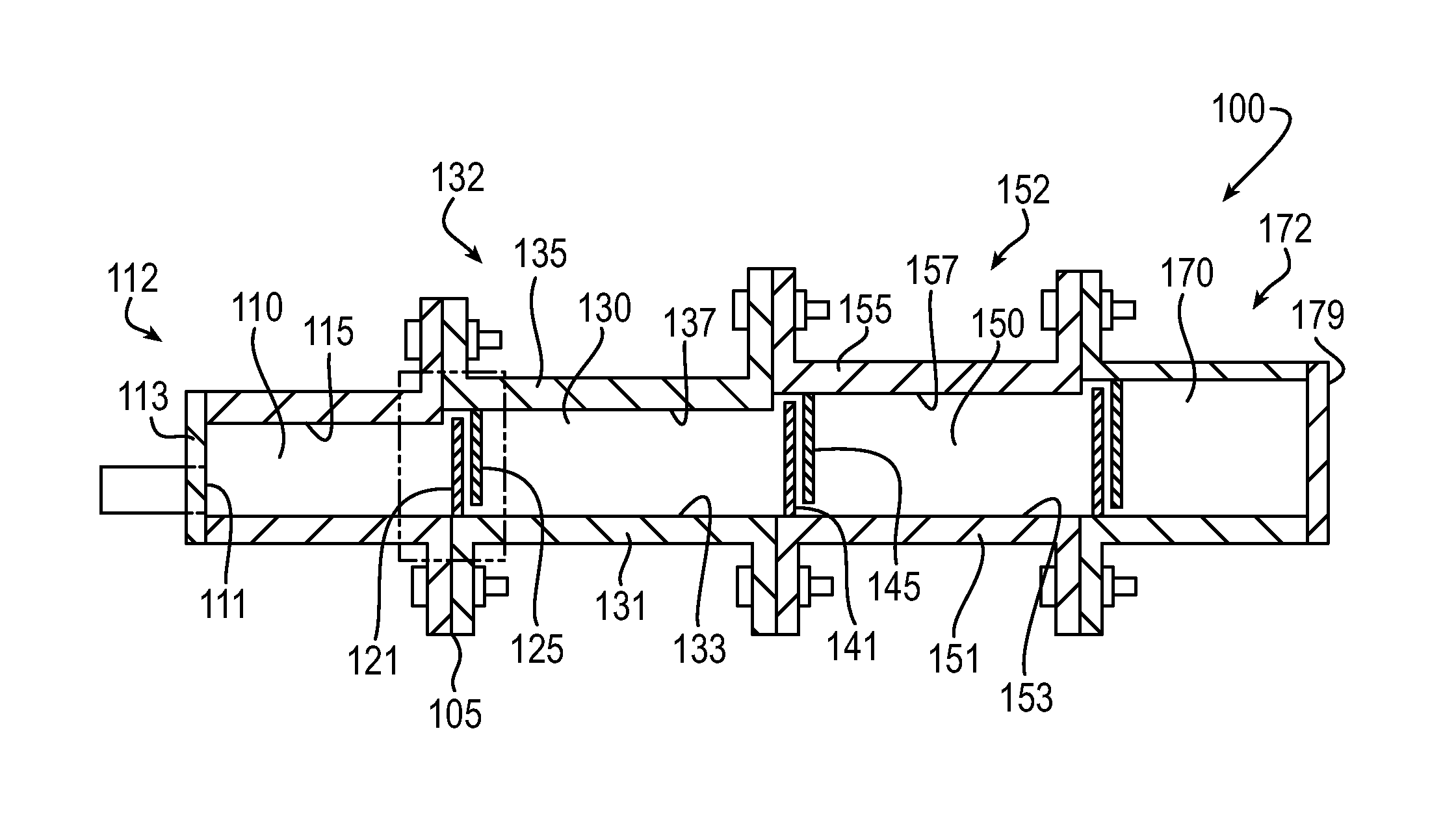
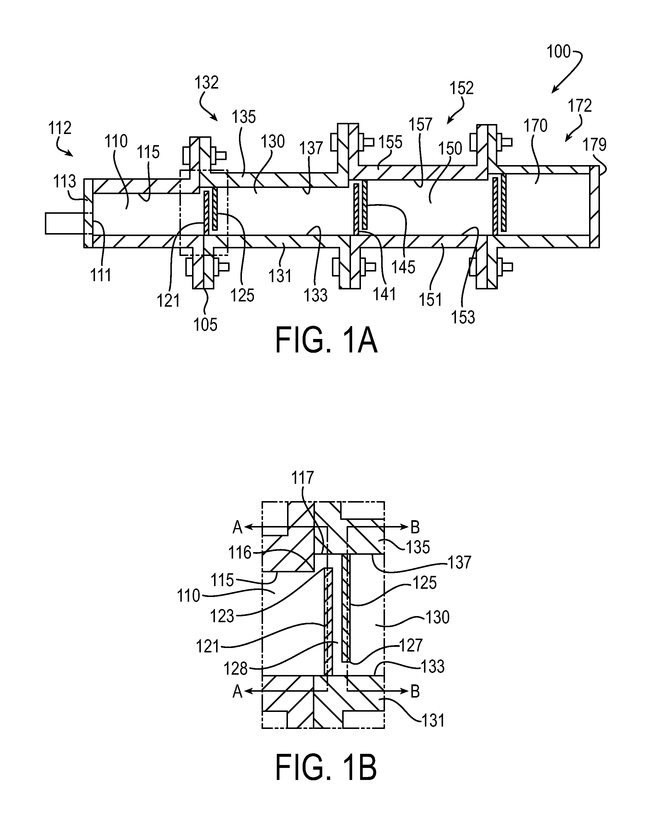
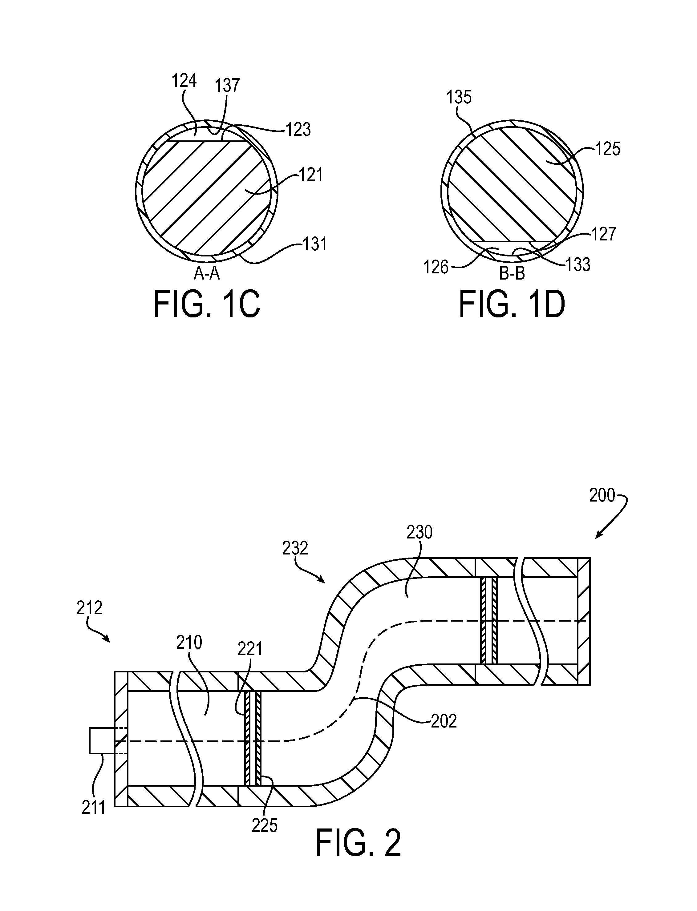
[0045]The principles of the present invention have particular application to non-barrier pressure reservoirs, also referred to as gas-over-fluid reservoirs, and thus will be described below chiefly in this context. For example, a non-barrier pressure vessel according to certain aspects of the invention may be useful on vehicle systems, such as land vehicle systems, including hydraulic hybrid vehicles that utilize a hydraulic system requiring a pressurized hydraulic fluid reservoir. Accordingly, the hydraulic fluid utilized in such exemplary systems is commonly based on oil, water, or other liquids; and the gas utilized in such systems may be nitrogen, air, or a combination of gases. It will of course be appreciated, and also understood, that principles of this invention may be applicable to other gas-over-fluid systems where it is desirable to allow trapped gas to naturally escape the fluid, while restricting the gas-fluid boundary from reaching the inlet / outlet.

[0046]In the discuss...


PUM

PropertyMeasurementUnit
pressureaaaaaaaaaa
lengthaaaaaaaaaa
cross-sectional areaaaaaaaaaaa

Abstract

A horizontal non-barrier pressure vessel including a first chamber and a second chamber that are separated by a divider. The first chamber includes a first end proximal an opening, a second end distal the opening, and an uppermost surface that extends horizontally along the length of the first chamber or is inclined upwardly from the first end to the second end. The second chamber operatively adjoins the first chamber at the second end opposite the opening. A flow passage extends across the divider and enables fluid communication with the first chamber at an upper region of the second end and with the second chamber at a lower region. The divider may include vertically oriented bottom and top baffles being spaced to form the flow passage. The pressure vessel may include a plurality of segments and/or chambers sequentially arranged along a horizontal course.

Description

RELATED APPLICATIONS[0001]This application claims the benefit of U.S. Provisional Application No. 62 / 105,484 filed Jan. 20, 2015, which is hereby incorporated herein by reference in its entirety.FIELD OF INVENTION[0002]The present invention relates generally to pressure vessels for hydraulic systems, and more particularly to non-barrier pressure reservoirs.BACKGROUND[0003]Pressurized vessels are used in hydraulic systems as reservoirs for the hydraulic working fluid. The pressurized reservoir not only acts as a source for storing hydraulic fluid, but can also act as a degassing system to allow trapped gas to escape from the hydraulic fluid. Therefore, pressurized reservoirs of this type are commonly used in the hydraulic systems of vehicles, such as hydraulic hybrid vehicles, because the degassing of the hydraulic fluid reduces cavitation in the hydraulic system pumps.[0004]Two types of pressurized reservoirs are generally known. A typical non-barrier-type reservoir includes a press...

Claims


Application Information

Patent Timeline
Patent Type & Authority Applications(United States)
IPC IPC(8): B01D19/00
CPCB01D19/0042F15B1/265F15B21/044F15B2211/00
Inventor CARL, BLAKE ADAM
Owner PARKER HANNIFIN CORP
Why Eureka
Try Eureka