Color signal processing circuit, color signal processing method, display device, and electronic apparatus
a color signal and processing circuit technology, applied in the field of color signal processing circuits, color signal processing methods, display devices, electronic devices, etc., to achieve the effect of reducing the data volume involved and less data volum
- Summary
- Abstract
- Description
- Claims
- Application Information
AI Technical Summary
Benefits of technology
Problems solved by technology
Method used
Image
Examples
first embodiment
3-1. First Embodiment
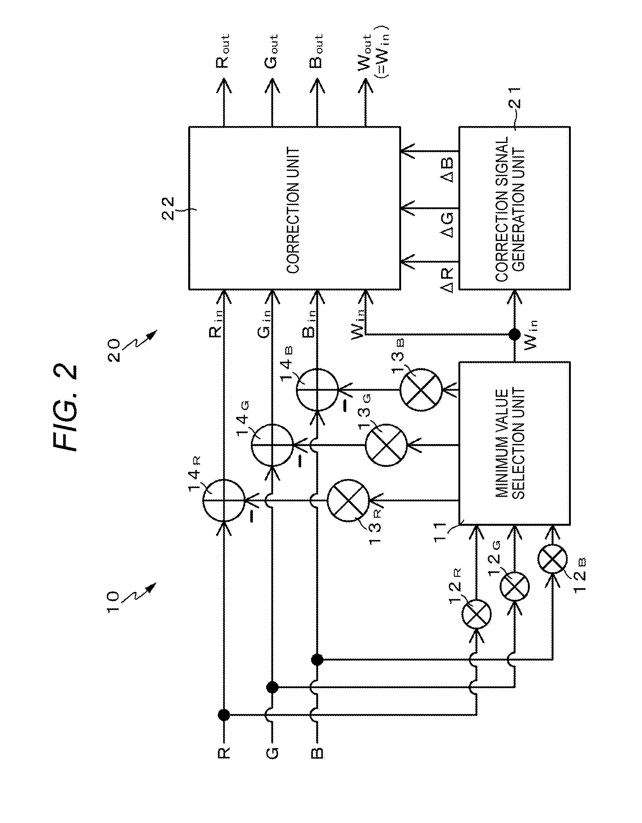
[0089]FIG. 3 is a block diagram illustrating a chromaticity change correction circuit (that is, a color signal processing circuit) according to first embodiment.
[0090]A chromaticity change correction circuit 20A according to the first embodiment is configured to use a look up table (LUT) 211A as a correction signal generation unit 21. The look up table 211A stores in advance the correction signals ΔR, ΔG, and ΔB found by executing the aforementioned first conversion function, the second conversion function, and the subtraction function in association with the signal level of the color signal Win of the white color. The correction signals ΔR, ΔG, and ΔB may take either a positive or negative value.
[0091]When the color signal Win of the white color is input to the look up table 211A, the correction signals ΔR, ΔG, and ΔB corresponding to the signal level of the color signal Win of the white color are output from the look up table 211A and then input to a correctio...
second embodiment
3-2. Second Embodiment
[0095]FIG. 4 is a block diagram illustrating a chromaticity change correction circuit (that is, a color signal processing circuit) according to second embodiment.
[0096]A chromaticity change correction circuit 20B according to the second embodiment specifies correction signals ΔR, ΔG, and ΔB output from a look up table 211B to take a positive value. Accordingly, adders 221R, 221G, and 221B of a correction unit 22B only perform addition processing.
[0097]However, it is concerned that the light emission luminance of a pixel increases as a result of addition of the correction signals ΔR, ΔG, and ΔB to color signals Rout, Gout, and Bout of the three primary colors when the value of the correction signals ΔR, ΔG, and ΔB output from the look up table 211A is restricted to take only the positive value.
[0098]In order to prevent the increase in the light emission luminance caused by the addition of the correction signals ΔR, ΔG, and ΔB to the color signals Rout, Gout and ...
third embodiment
3-4. Third Embodiment
[0106]FIG. 6 is a block diagram illustrating a chromaticity change correction circuit (that is, a color signal processing circuit) according to third embodiment.
[0107]A chromaticity change correction circuit 20D according to the third embodiment is based on the configuration of the chromaticity change correction circuit 20A according to the first embodiment and is configured to use a plurality of look up tables as a look up table 211D. The look up table 211D is formed of the plurality of look up tables as well in fourth and fifth embodiments to be described later. This can also be applied to a case where the chromaticity change correction circuit 20D is based on the configuration of the chromaticity change correction circuit 20B according to the second embodiment or the chromaticity change correction circuit 20C according to the variation of the second embodiment.
[0108]Where the plurality of look up tables is used as the look up table 211D, the chromaticity chan...
PUM
 Abstract
Description
Claims
Application Information
 - R&D
- Intellectual Property
- Life Sciences
- Materials
- Tech Scout
- Unparalleled Data Quality
- Higher Quality Content
- 60% Fewer Hallucinations
Browse by: Latest US Patents, China's latest patents, Technical Efficacy Thesaurus, Application Domain, Technology Topic, Popular Technical Reports.
© 2025 PatSnap. All rights reserved.Legal|Privacy policy|Modern Slavery Act Transparency Statement|Sitemap|About US| Contact US: help@patsnap.com


