Laser welded firearm sound suppressors

a technology of sound suppressor and laser welding, which is applied in the field of sound suppressor, can solve the problems of bending, warping, or other misalignment of the constituent suppressor components, and the conventional welding technique is problematic for sound suppressor applications, and achieves the effect of reducing the number of sound suppressors

Active Publication Date: 2016-07-21
SUREFIRE LLC
View PDF6 Cites 24 Cited by
  • Summary
  • Abstract
  • Description
  • Claims
  • Application Information

AI Technical Summary

Benefits of technology

[0010]In accordance with the present disclosure, novel firearm sound suppressors are provided, together with methods for assembling them reliably, accurately and in a cost-effective manner using laser welding techniques.
[0013]In another example embodiment, a sound suppressor for a firearm includes a plurality of baffles; a plurality of spacers; a substantially tubular housing surrounding the baffles and the spacers; wherein the housing and the spacers define an annular volume surrounding the spacers; an aperture in a circumfery of at least one of the spacers; and wherein the aperture is adapted to direct combustion gases in a radial direction from within the spacer into the annular volume to reduce ejection port flash of the firearm.

Problems solved by technology

However, such conventional welding techniques are problematic for sound suppressor applications.
For example, conventional welding techniques typically require the various suppressor components to be exposed to high heat for extended periods of time while each welding operation is performed.
This exposure results in associated bending, warping, or other misalignment of the constituent suppressor components.
After the components are realigned, another weld is performed, resulting in an associated misalignment and followed by another forced realignment of the suppressor components.
These repeated misalignments and associated corrective realignments take significant time (e.g., up to 20 minutes of longer for each suppressor), cause undesirable stress on the suppressor components, and are generally inefficient.

Method used


Image

  • Laser welded firearm sound suppressors
  • Laser welded firearm sound suppressors
  • Laser welded firearm sound suppressors

Examples


Embodiment Construction

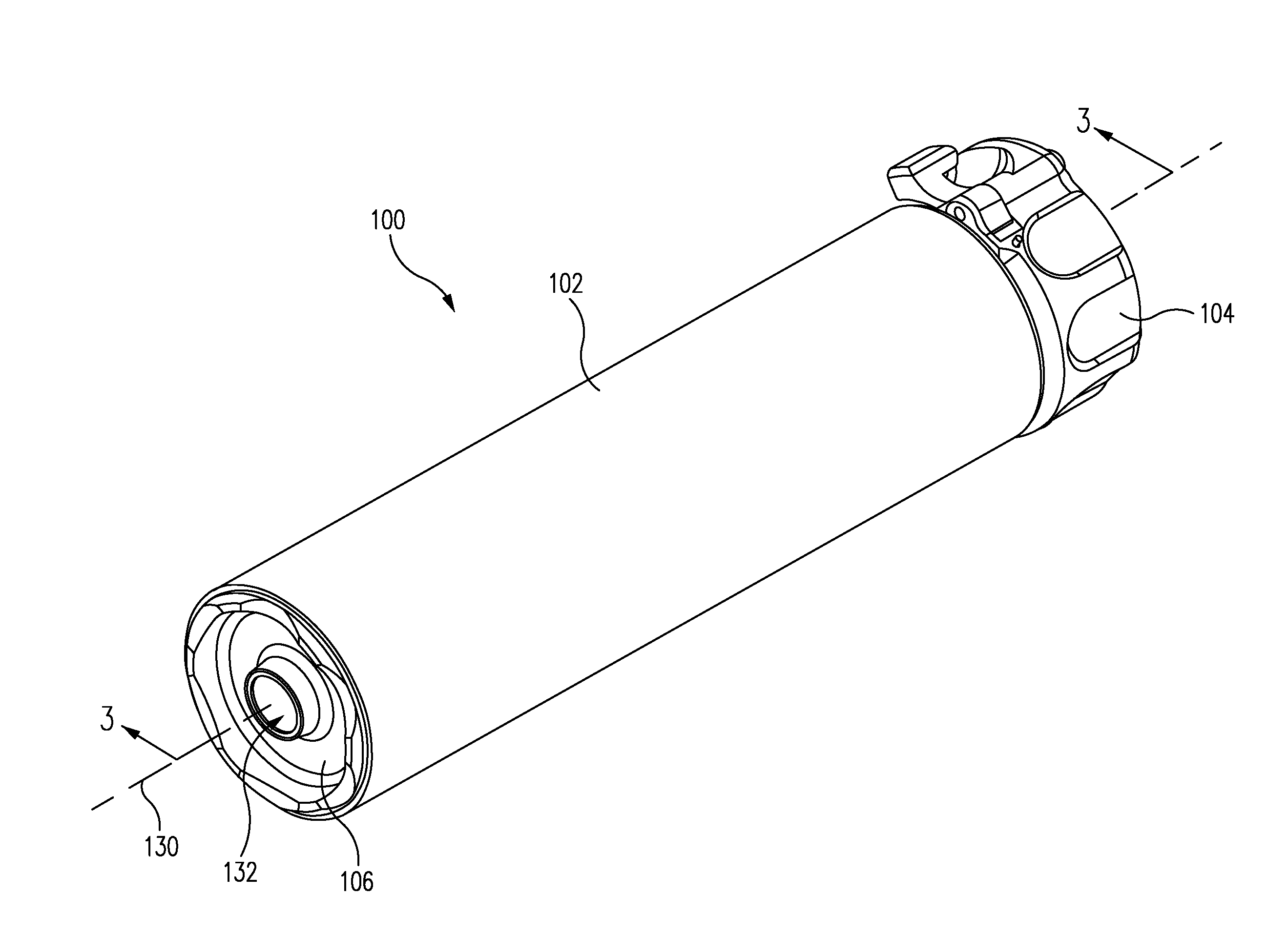
[0023]In accordance with the present disclosure, novel firearm sound suppressors are provided, together with example methods for assembling them reliably, accurately, and in a cost-effective manner using laser welding techniques.

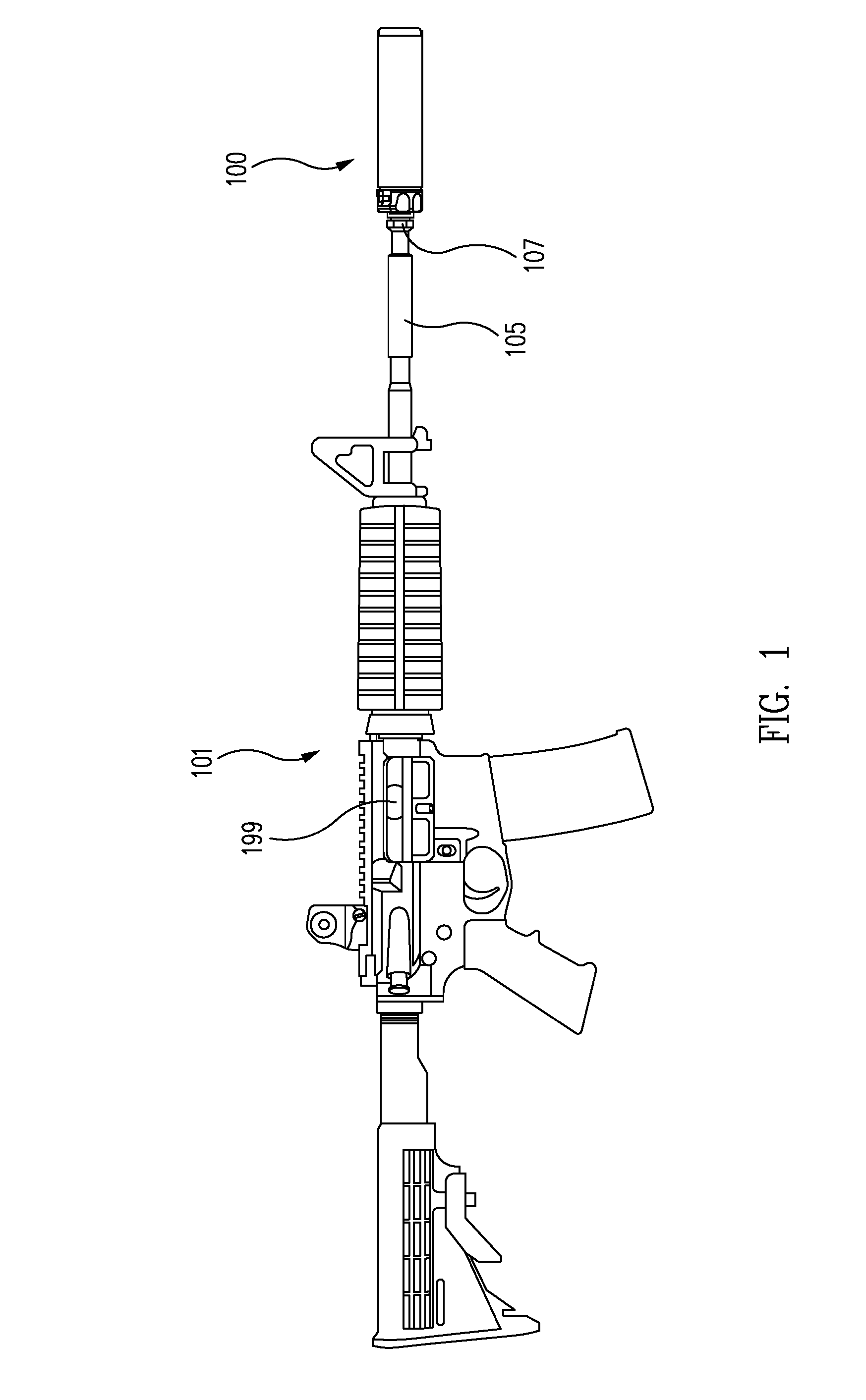
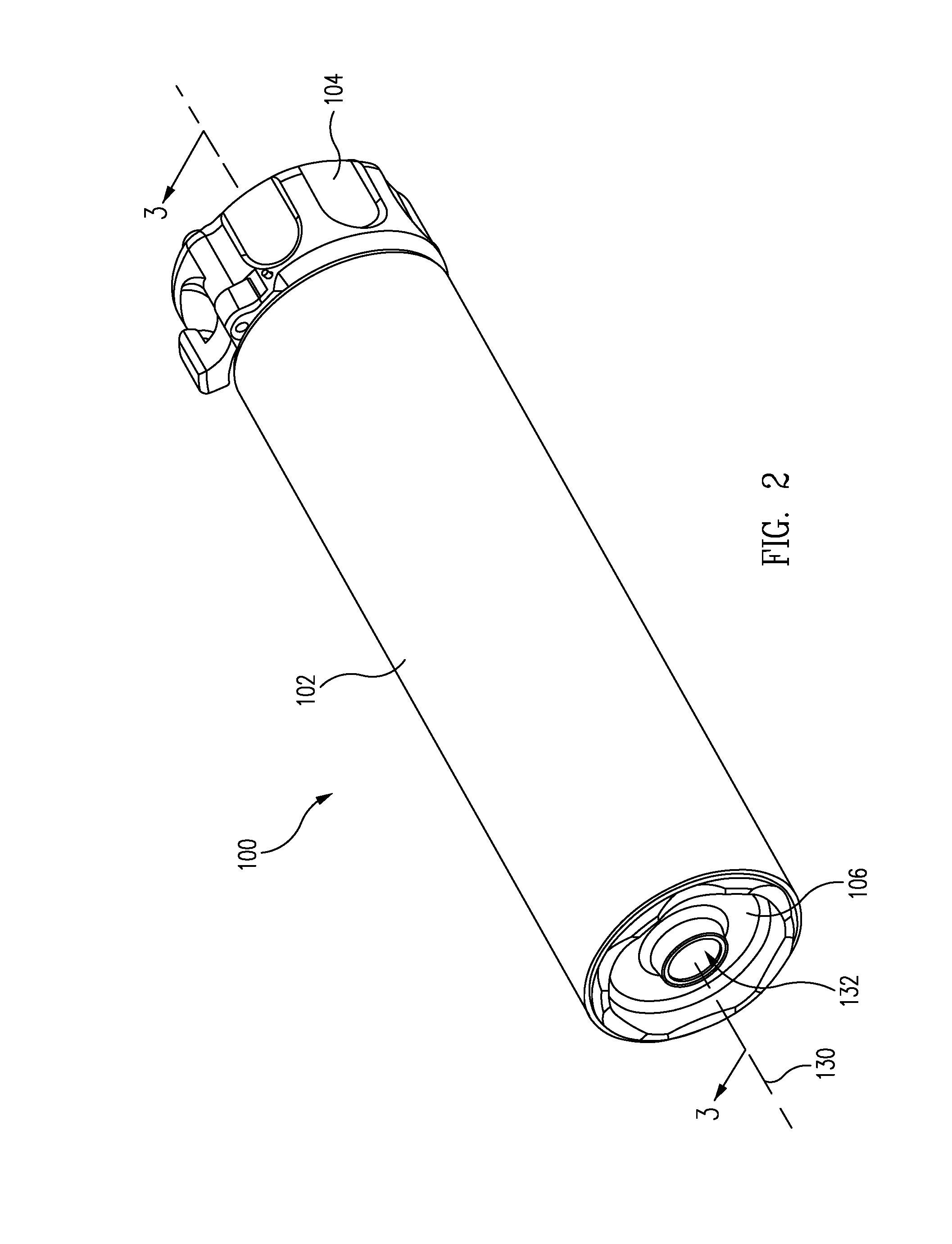
[0024]An example embodiment of a firearm sound suppressor 100 in accordance with the present disclosure is illustrated in FIGS. 1 to 4. FIG. 1 is a right side elevation view of a firearm 101, e.g., a rifle, having a sound suppressor 100 coupled to the muzzle end of a barrel 105 of the firearm 101 in accordance with the present disclosure. FIG. 2 is a front, upper, and left side isometric view of the example suppressor 100, and FIG. 3 is a cross-sectional view of the suppressor 100 of FIG. 2, as seen along the lines of the section 3-3 taken therein. FIG. 4 is a front, upper, and left side isometric view of the suppressor 100 of FIG. 2 with a tubular housing 102 and retaining mechanism 104 both removed therefrom to reveal a welded assembly (e.g., also referred...


PUM

PropertyMeasurementUnit
diameteraaaaaaaaaa
diameteraaaaaaaaaa
circumferential diameteraaaaaaaaaa

Abstract

Various techniques are provided to assemble, manufacture, and operate firearm sound suppressors. In one example, a sound suppressor for a firearm includes a baffle; a spacer abutted to the baffle; and a circumferential laser weld joining the baffle and the spacer. In another example, a sound suppressor for a firearm includes a plurality of baffles; a plurality of spacers; a substantially tubular housing surrounding the baffles and the spacers; wherein the housing and the spacers define an annular volume surrounding the spacers; an aperture in a circumfery of at least one of the spacers; and wherein the aperture is adapted to direct combustion gases in a radial direction from within the spacer into the annular volume to reduce ejection port flash of the firearm. Additional suppressor embodiments and related methods are also provided.

Description

CROSS-REFERENCE TO RELATED APPLICATIONS[0001]This application claims priority to and the benefit of U.S. Provisional Patent Application No. 62 / 104,354 filed Jan.16, 2015 and entitled “LASER WELDED FIREARM SOUND SUPPRESSORS” which is hereby incorporated by reference in its entirety.BACKGROUND[0002]1. Technical Field[0003]This application relates to sound suppressors for firearms in general, and in particular, to techniques for assembling components of firearm sound suppressors using laser welding techniques.[0004]2. Related Art[0005]Firearms, such as pistols, rifles, submachine guns and machine pistols, utilize expanding high-pressure gases generated by a burning propellant to expel a projectile from the weapon at a relatively high velocity. When the projectile, or bullet, exits the muzzle end of the weapon's barrel, a bright, “muzzle flash” of light and a high-pressure pulse of combustion gases accompany it. The rapid pressurization and subsequent depressurization caused by the high...

Claims


Application Information

Patent Timeline
Patent Type & Authority Applications(United States)
IPC IPC(8): F41A21/30B23K26/282
CPCF41A21/30B23K26/282F41A21/34
Inventor DUECK, BARRY W.RADGOWSKI, DENNISBROWN, KAVANHONIGMANN, KARL R.
Owner SUREFIRE LLC
Why Eureka
Try Eureka