System capable of immediately performing operation on workpiece
a workpiece and workpiece technology, applied in the direction of programmed manipulators, manufacturing tools, transportation and packaging, etc., can solve the problem of not providing a configuration that prevents heat influence, and achieve the effect of reducing temperature variation, preventing the relative position of the floor from being changed, and reducing the influence of floor vibration
- Summary
- Abstract
- Description
- Claims
- Application Information
AI Technical Summary
Benefits of technology
Problems solved by technology
Method used
Image
Examples
first embodiment
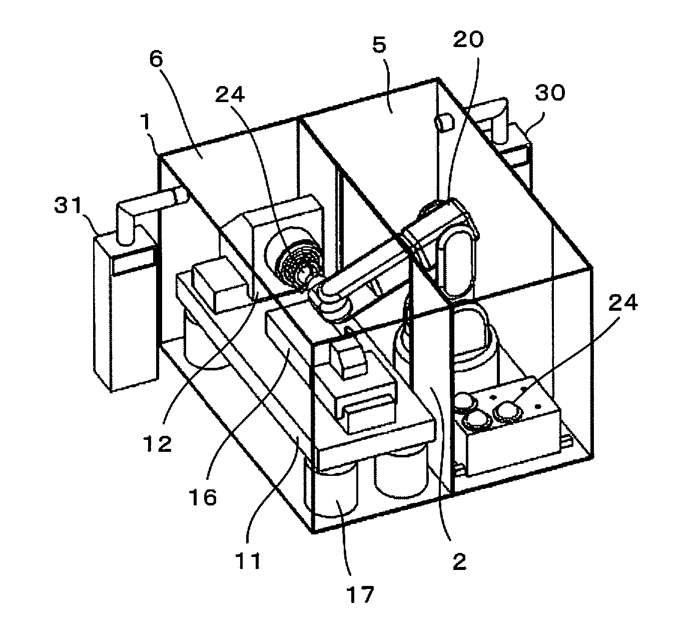
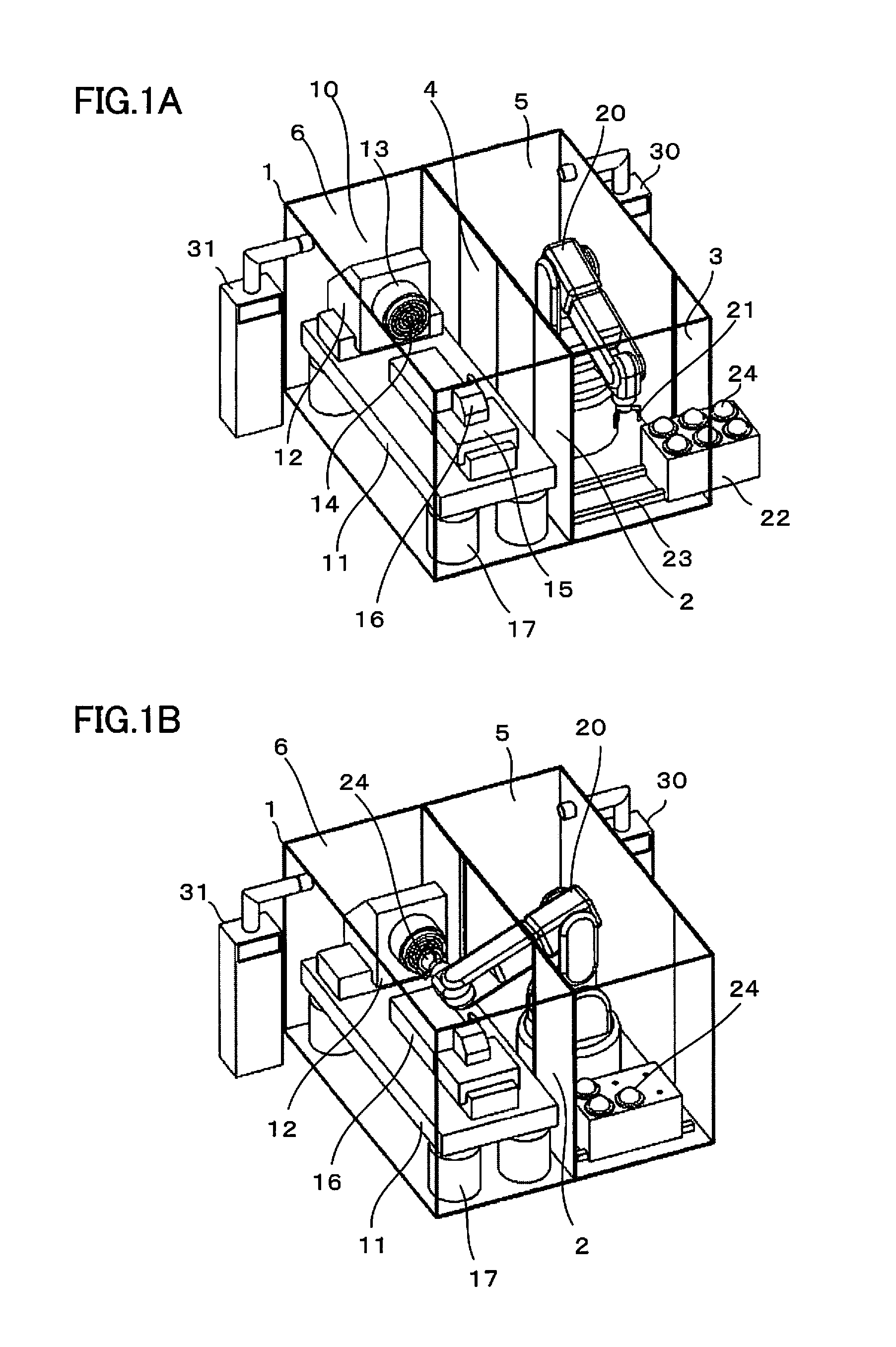
[0031]First, a system capable of immediately performing work on a workpiece according to the present invention will be described using FIGS. 1A and 1B. In this embodiment, as a device that performs work on a workpiece, which constitutes the system, a precision lathe is used.
[0032]In FIG. 1A, a first door 3 to be opened and closed by a first open / close mechanism (not shown) is in an open state, through which a workpiece 24 is supplied from outside the device to a front chamber 5, and a second door 4 to be opened and closed by a second open / close mechanism (not shown) is in an closed state to isolate the front chamber 5 and a main chamber 6 from each other.
[0033]The front chamber 5 and main chamber 6 are formed by a cover 1. A space defined by the cover 1 is partitioned by a partition cover 2 into the front chamber (first space) 5 and main chamber (second space) 6. The cover 1 has an opening portion, to which the first door 3 configured to be freely opened by the first open / close mech...
second embodiment
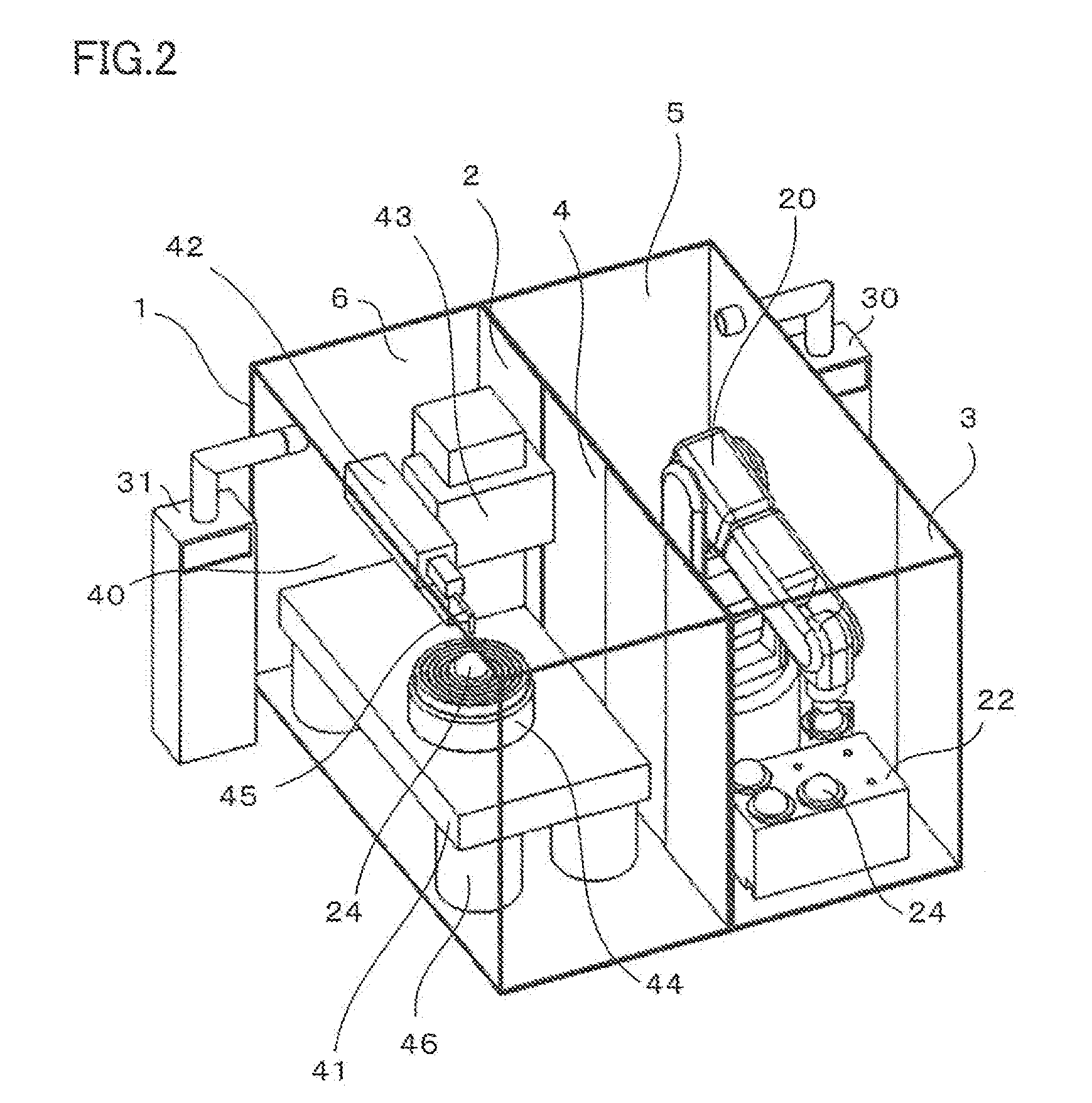
[0042]Next, a system capable of immediately performing work on a workpiece according to the present invention will be described using FIG. 2. In this embodiment, as a device that performs work on a workpiece, which constitutes the system, a precision three-dimensional measurement device is used.
[0043]As in the system described using FIGS. 1A and 1B, the system according to the second embodiment includes the robot 20, cover 1, front chamber 5, main chamber 6, first air conditioner 30, and second air conditioner 31. A Z-axis (front-rear slide 42) is mounted on a Y-axis (up-down slide 43) on a base 41, a measurement probe 45 of a precision three-dimensional measurement device 40 fitted to a leading end of the Z-axis (front-rear slide 42) is brought into contact with the workpiece 24 to measure a shape thereof. Further, there is mounted, on the base 41, a rotary table 44 to which the workpiece 24 is fixed through a vacuum chuck (not shown).
[0044]The precision three-dimensional measureme...
third embodiment
[0045]Next, a system capable of immediately performing work on a workpiece according to the present invention will be described using FIG. 3. In this embodiment, a precision lathe as a device that performs work on a workpiece is mounted on a base provided with a vibration eliminating device (that is, on a base placed on a vibration-free table) together with the robot.
[0046]As illustrated in FIG. 3, when the robot 20 is mounted on a base 18 placed on a vibration-free table 19, a reach of an arm of the robot 20 required for replacement of the workpiece 24 can be made smaller than a case where the robot 20 is installed on a floor, so that it is possible to make the robot 20 compact in size by the corresponding amount, which offers an advantage in cost. Further, an occupied area of the robot 20 with respect to the floor is reduced, so that an installation area of the entire system can be reduced. Further, the vibration-free table 19 has often no reproducibility in position (posture); ho...
PUM
 Abstract
Description
Claims
Application Information
 - R&D
- Intellectual Property
- Life Sciences
- Materials
- Tech Scout
- Unparalleled Data Quality
- Higher Quality Content
- 60% Fewer Hallucinations
Browse by: Latest US Patents, China's latest patents, Technical Efficacy Thesaurus, Application Domain, Technology Topic, Popular Technical Reports.
© 2025 PatSnap. All rights reserved.Legal|Privacy policy|Modern Slavery Act Transparency Statement|Sitemap|About US| Contact US: help@patsnap.com


