Array substrate, method for controlling the same, liquid crystal display device

a liquid crystal display device and array substrate technology, applied in the field of touch liquid crystal display, can solve the problems of increasing the number of patterning processes, increasing production costs, and affecting the light transmittance of the display panel, so as to avoid the decrease in the light transmittance simplify the structure of the liquid crystal display device

Active Publication Date: 2016-07-28
BOE TECH GRP CO LTD +1
View PDF1 Cites 9 Cited by
  • Summary
  • Abstract
  • Description
  • Claims
  • Application Information

AI Technical Summary

Benefits of technology

[0018]Embodiments of the present invention provide an array substrate, a method for controlling the same, and a liquid crystal display device comprising the same. The array substrate comprises a substrate, a plurality of transistors which are arranged on the substrate, a first transparent electrode which is electrically connected with a drain of the transistor, and a second transparent electrode which is arranged between the first transparent electrode and the substrate; the first transparent electrode comprises a plurality of strip-shaped electrodes which are electrically connected with each other; the second transparent electrode comprises a plurality of electrode sets which are arranged in the same layer and insulated from each other, each electrode set comprises two sub-electrodes which are insulated from each other and arranged in a staggered and complementary manner, and each sub-electrode corresponds to a plurality of the first transparent electrodes; wherein the sub-electrodes act as a common electrode in a first preset time and a touch control electrode in a second preset time. Since the second transparent electrode is arranged as a plurality of electrode sets which are insulated from each other, and each electrode set comprises sub-electrodes which are insulated from each other and arranged in a staggered and complementary manner, it is possible for the sub-electrodes to act as the common electrode in the first preset time and the touch control electrode in the second preset time. In this way, it is not necessary to provide additional patterned layers to integrate the touch control electrode in the array substrate. In case the array substrate is applied to the liquid crystal display device, the display and touch control function can be realized, thus simplifying structure of the liquid crystal display device. In addition, since it is not necessary to provide additional patterned layers to integrate the touch control electrode in the array substrate, it is possible to avoid decrease in light transmittance of the liquid crystal display device.

Problems solved by technology

This not only increases the number of patterning processes, which leads to increase in production cost, but also affects the light transmittance of the display panel.

Method used


Image

  • Array substrate, method for controlling the same, liquid crystal display device
  • Array substrate, method for controlling the same, liquid crystal display device
  • Array substrate, method for controlling the same, liquid crystal display device

Examples


Embodiment Construction

[0027]Several technical solutions of the present disclosure will be described in more detail below with reference to the accompanying drawings in order for those skilled in the art to be able to carry out the present disclosure. The present disclosure may, however, be embodied in many different forms and should not be construed as limited to embodiments set forth herein. These embodiments do not limit the present disclosure, but the present disclosure is only limited by the appended claims.

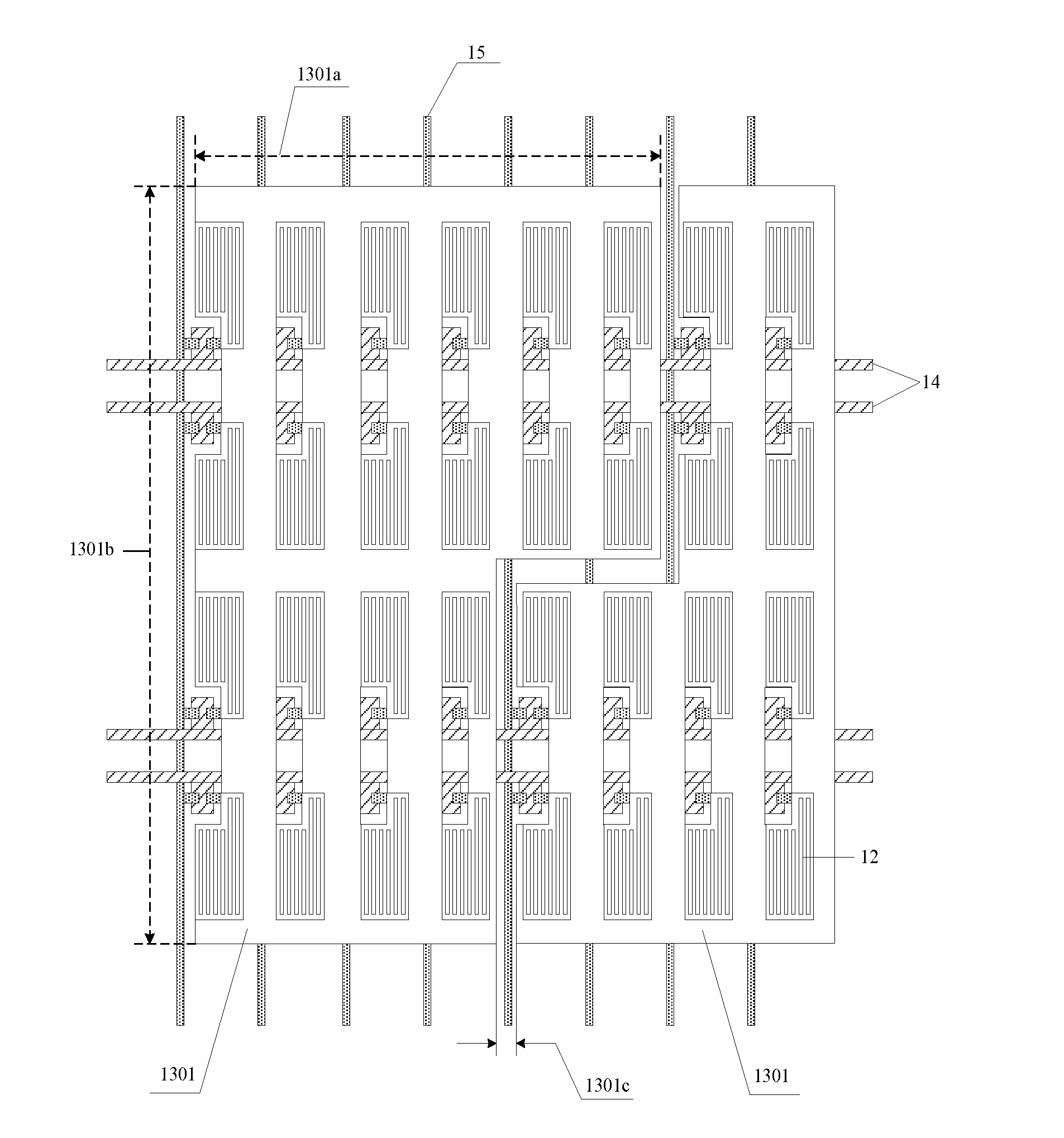
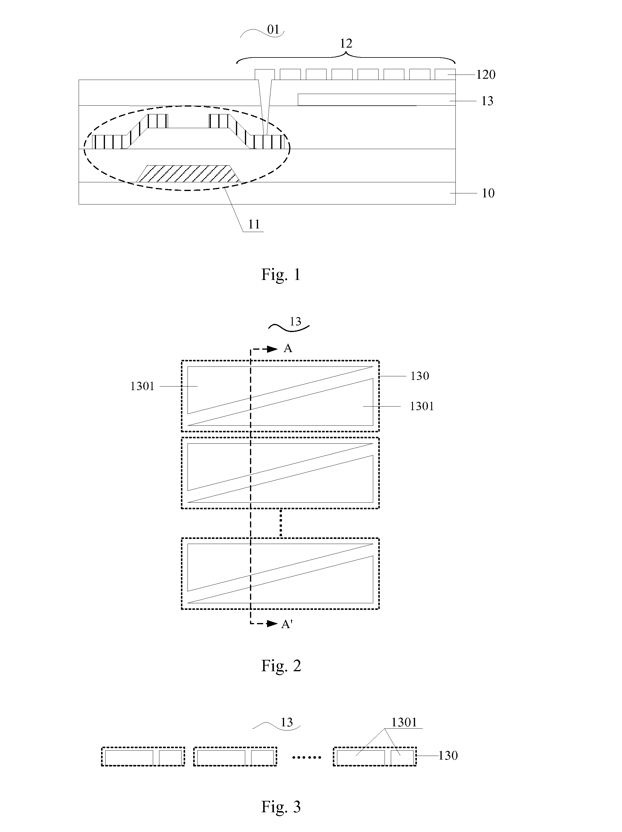
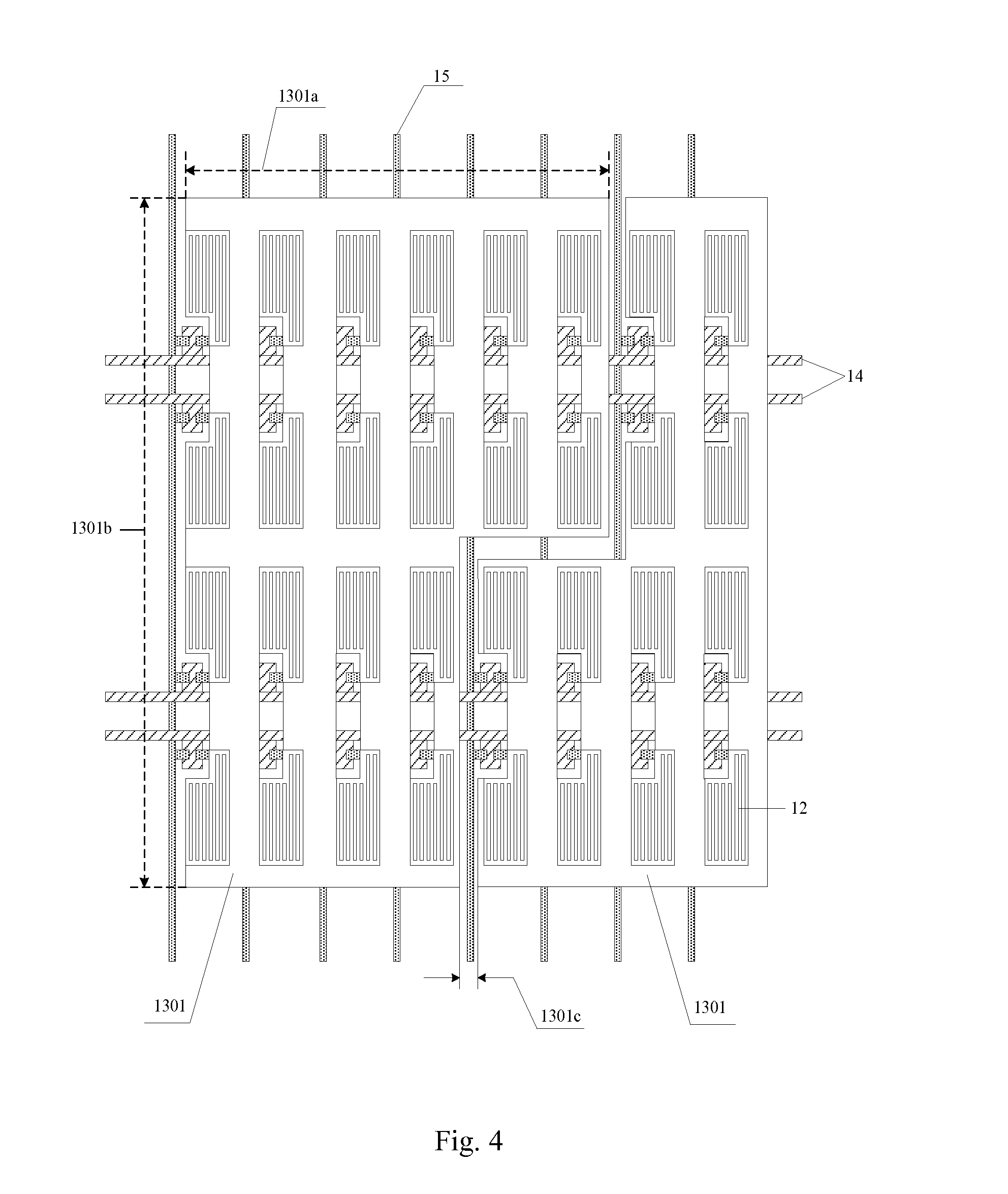
[0028]The reference numerals in drawings are explained as follow: 01 array substrate; 10 substrate; 11 transistor; 12 first transparent electrode; 120 strip-shaped electrode; 13 second transparent electrode; 130 electrode set; 1301 sub-electrode; 1301a first right-angle side; 1301b second right-angle side; 1301c interval; 14 gate line; 15 data line; 16 secondary metal wires; 160 via hole; 17 primary metal wire; 02 color film substrate; and 03 liquid crystal layer.

[0029]Embodiments of the present i...


PUM

PropertyMeasurementUnit
widthaaaaaaaaaa
lengthaaaaaaaaaa
constant voltageaaaaaaaaaa

Abstract

An array substrate comprises a substrate, transistors arranged on the substrate, a first transparent electrode electrically connected with a drain of the transistor, and a second transparent electrode arranged between the first transparent electrode and the substrate. The first transparent electrode comprises strip-shaped electrodes electrically connected with each other. The second transparent electrode corresponds to the first transparent electrode and comprises electrode sets insulated from each other. Each of the plurality of electrode sets comprises two sub-electrodes arranged in the same layer, insulated from each, and arranged in a staggered and complementary manner. The sub-electrodes of the second transparent electrode act as a common electrode in a first preset time and a touch control electrode in a second preset time. A method for controlling the array substrate and a liquid crystal display device are also disclosed. The touch control function can be integrated in the array substrate, simplifying structure of the display device.

Description

FIELD OF THE INVENTION[0001]The present invention relates to the field of technique for touch liquid crystal display, and particularly to an array substrate, a method for controlling the same, and a liquid crystal display device comprising the same.BACKGROUND ART[0002]Due to the rapid development of the display technique, the advent of touch panel (TP) brings the user a more convenient life.[0003]The touch panel comprises an Add-On touch panel and an In-Cell touch panel. In the In-Cell touch panel, a touch panel with a touch sensor (i.e., a touch driving electrode and a touch sensing electrode) is integrated in the display panel, and generally is arranged between the array substrate and the liquid crystal layer of the display panel. In the In-Cell touch panel, it is possible to realize a display touch panel which has the display and touch control function and is simply in structure.[0004]The touch sensing for the In-Cell touch panel is conducted in a capacitance mode, which can be f...

Claims


Application Information

Patent Timeline
Patent Type & Authority Applications(United States)
IPC IPC(8): G06F3/041G06F3/044G02F1/1333G02F1/1368G02F1/1343
CPCG06F3/0412G02F1/1368G02F1/13439G02F1/134309G06F2203/04111G06F3/0416G06F3/044G02F2001/134345G02F1/13338G02F1/134363G06F3/04164G06F3/04166G06F3/0443G02F1/134372G02F1/134345
Inventor YANG, SHENGJI
Owner BOE TECH GRP CO LTD
Why Eureka
Try Eureka