Method and system for damping torsional oscillations

a technology of torsional oscillation and damping system, which is applied in the direction of electric generator control, machines/engines, mechanical equipment, etc., can solve the problems of changing the demand on the generator, damage to the drive line, and nothing to address the problem, so as to simplify the control of the oscillation and avoid the complications of the system. , the effect of decoupling the transfer

Inactive Publication Date: 2016-07-28
ROLLS ROYCE PLC
View PDF9 Cites 20 Cited by
  • Summary
  • Abstract
  • Description
  • Claims
  • Application Information

AI Technical Summary

Benefits of technology

[0025]The proposed control method can also be applied to a gas turbine connected with multiple generators or motors such that more than one driveline is present within the system. Control signals may then be provided to each generator or motor based on the oscillations determined in each driveline. This helps to avoid complications within the system resulting from interactions between drivelines and thus simplifies control of the oscillations.
[0026]In addition to the direct benefit resulted from torsional vibration damping, the proposed disclosure has added benefits due to use of a power electronics converter. Generators that are connected in different shafts can be paralleled generators, DC aircraft electrical loads etc. The disclosure would help to decouple the generator operation from the airframe frequency and voltage requirement. The disclosure can also decouple the transfer of oscillation and disturbance from one system to another, and this can improve the power quality of airframe and also prevent unwanted harmonics passing into the mechanical system.

Problems solved by technology

This, however, does nothing to address the problem when the demand on the generator is changed, as it will be when it is dictated that a change is small and / or non-transient.
As a result, oscillations can still build up in the system and the cause damage to the drive line.
However, in particular in the context of aerospace applications, the acceptable size and weight of the auxiliary power supply is limited so that some changes in demand will inevitably lead to changes in demand on the generator.

Method used


Image

  • Method and system for damping torsional oscillations
  • Method and system for damping torsional oscillations
  • Method and system for damping torsional oscillations

Examples


Embodiment Construction

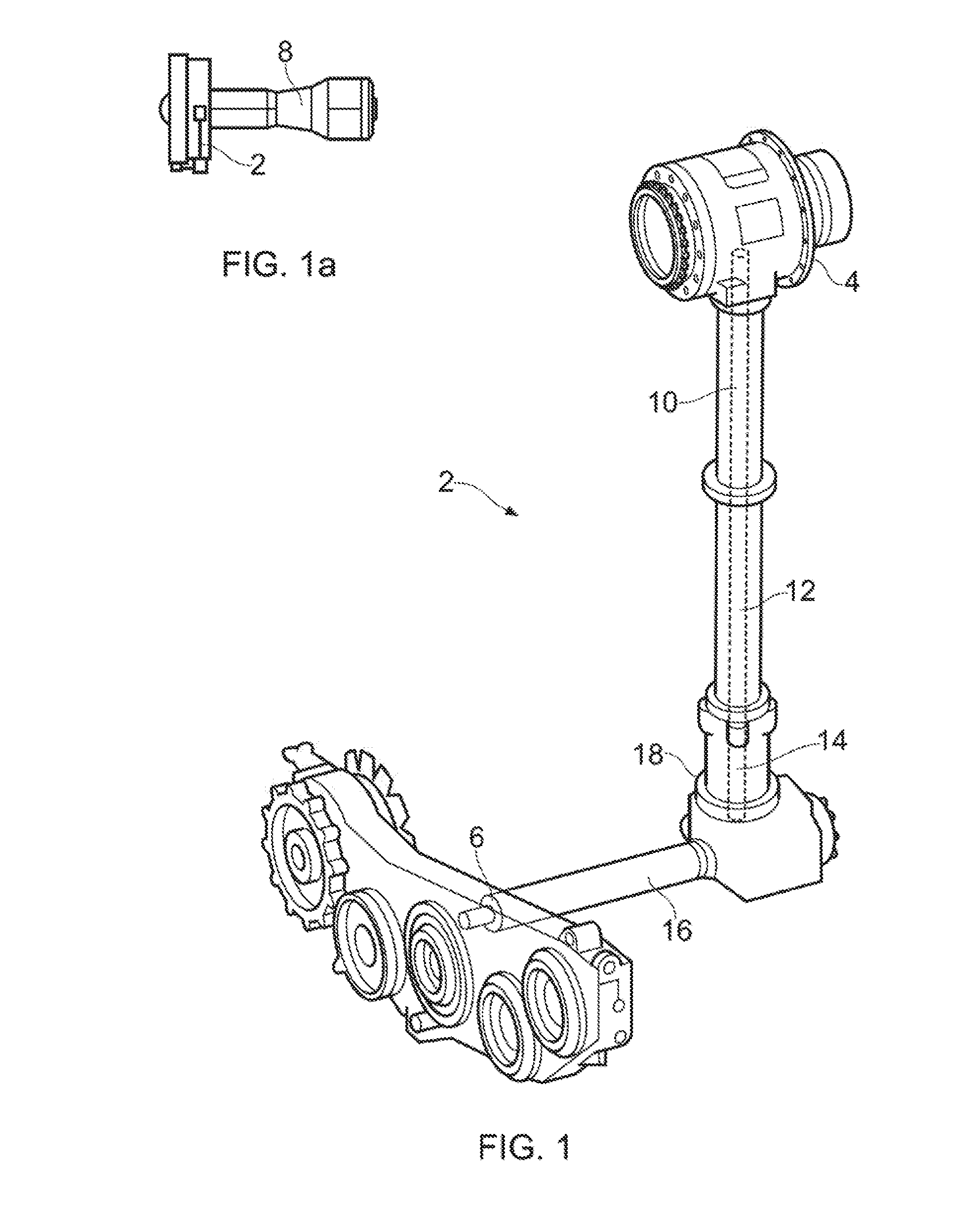
[0039]FIG. 1 shows a gearbox and shaft arrangement 2 for driving one or more generators. An inlet gearbox 4 is located, in use, within the core of a gas turbine engine. The generators are located together with other rotating loads such as fuel pump and oil pump as shown in an accessory gearbox 6 mounted on the fan casing or core casing of gas turbine engine 8 as illustrated in FIG. 1a. Mechanical power transmission from the inlet gearbox 4 to the accessory gearbox 6 is achieved through a driveline consisting of a number of torsionally flexible shafts 10,12,14,16, and a transfer gearbox 18. Due to the presence of elasticity in the shafts 10,12,14,16 and gearbox 18, this arrangement can suffer from torsional oscillations, which can be detrimental to the overall system performance and the life of the components.

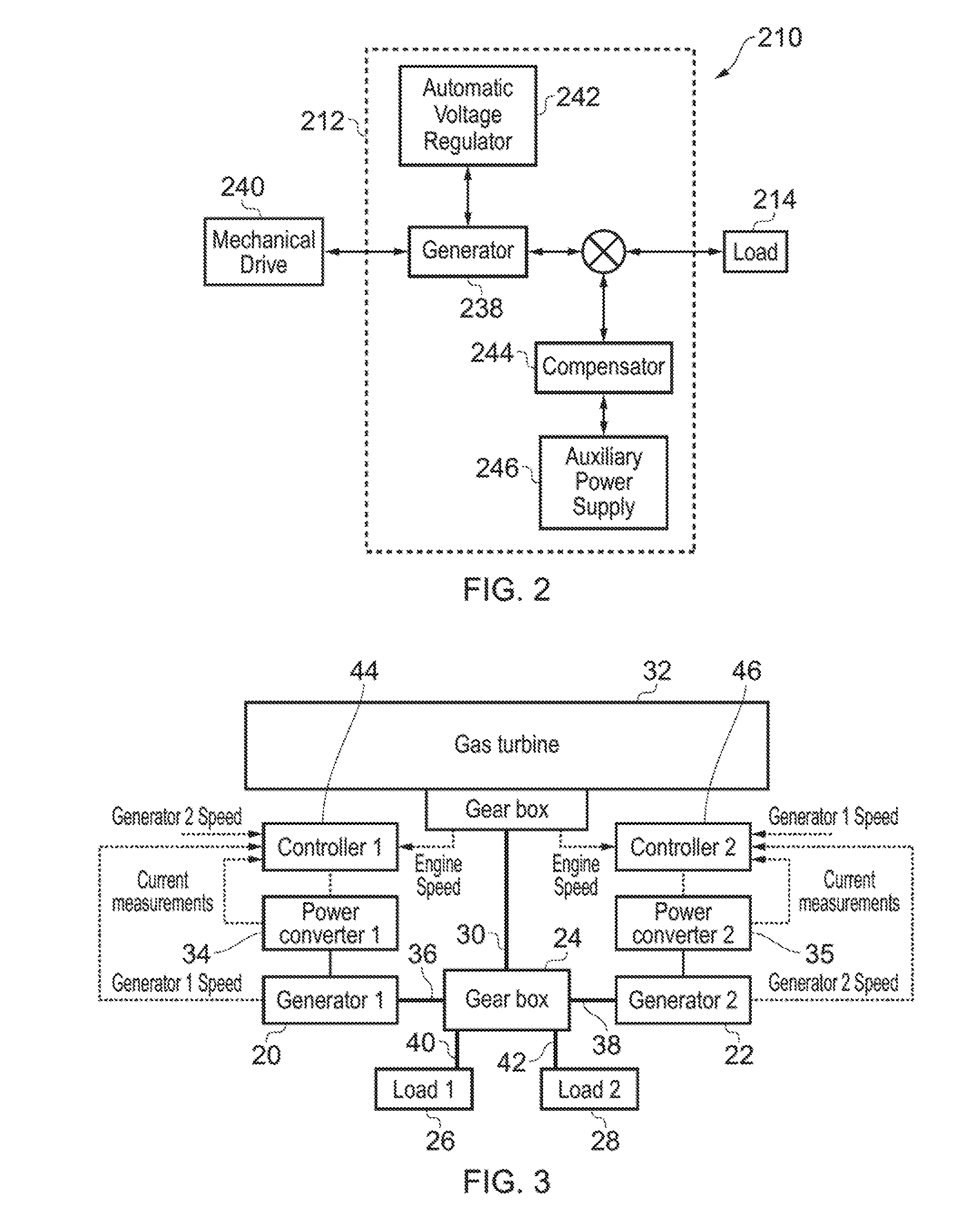
[0040]FIG. 2, taken from US 2012 / 0104842, shows a system level diagram of a known control method designed to address the problem of oscillations in a generator driveline. The di...


PUM


Abstract

The invention concerns the damping of torsional oscillations/vibrations, particularly during electrical power generation within a gas turbine such as a civil aviation engine. The method of the invention relies on actively generating compensating oscillations in a driveline of a system to actively damp undesirable oscillations existing in the system.

Description

[0001]This disclosure claims the benefit of UK Patent Application No. GB 1501135.6, filed on 23 Jan. 2015, which is hereby incorporated by reference herein in its entirety.FIELD OF THE DISCLOSURE[0002]The present disclosure relates to the damping of torsional oscillations / vibrations and particularly, but not exclusively, to the damping of torsional oscillations / vibrations during electrical power generation within a gas turbine such as a civil aviation engine.BACKGROUND OF THE DISCLOSURE[0003]The increased desire for electrical power in both civil and defence aircraft has led to an increase in aircraft on-board power generation. Typically, one or more electrical generators is connected into the gas turbine through a driveline consisting of slender shafts and a gear train that would transmit the power across multiple generators and other supporting systems, such as an oil pump and / or fuel pump, which are mounted in the fan casing. However, drive line flexibility makes the system susce...

Claims


Application Information

Patent Timeline
Patent Type & Authority Applications(United States)
IPC IPC(8): H02P9/10F01D15/12F01D25/04F01D15/10
CPCH02P9/102F01D15/10F01D15/12F05D2260/40311F05D2220/30F05D2260/96F01D25/04F16F15/002F16F15/18
Inventor GAJANAYAKE, CHANDANA JAYAMPATHIGUPTA, AMIT KUMARSLATER, ROBERTBHANGU, BIKRAMJITFOO, GILBERT HOCK BENGVILATHGAMUWA, DON MAHINDA
Owner ROLLS ROYCE PLC
Why Eureka
Try Eureka