
Fall detection system and method

Active Publication Date: 2016-08-04
KONINKLJIJKE PHILIPS NV
View PDF32 Cites 51 Cited by
  • Summary
  • Abstract
  • Description
  • Claims
  • Application Information

AI Technical Summary

Benefits of technology

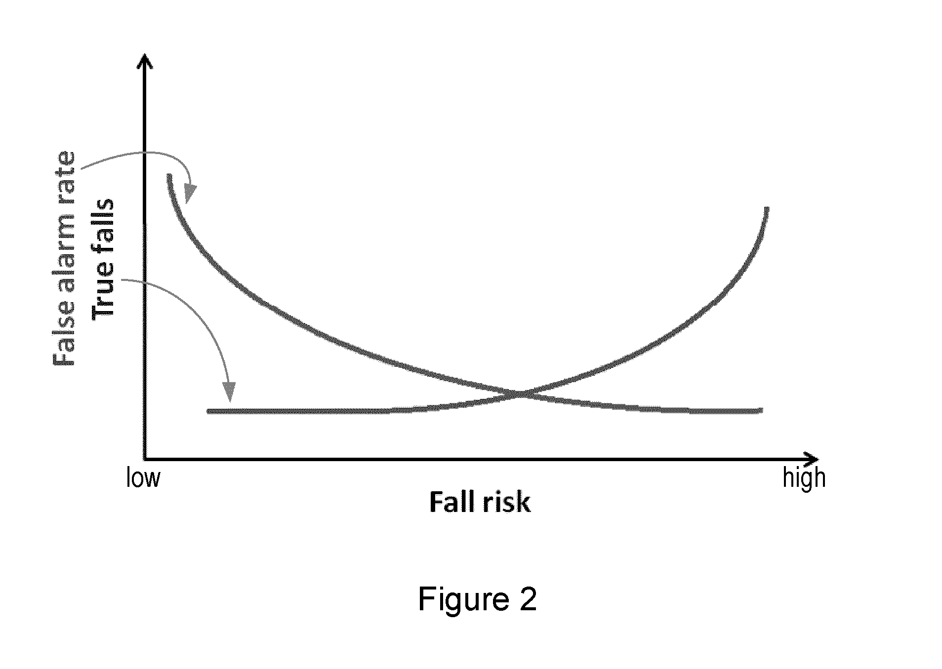
The invention relates to a technology that adjusts the sensitivity of a fall detection algorithm based on the user's environment and the user's contextual information. If the user is at a higher risk of falling, the sensitivity of the algorithm is increased to detect more falls. This increased sensitivity is temporary and only for as long as the higher risk of falling is present or detected. The technology decreases the sensitivity if the user is at a decreased risk of falling, reducing the likelihood of false alarms. Overall, this technology allows for accurate detection of falls while minimizing false alarms.

Problems solved by technology

Therefore most falls in this group happen as a consequence of fast movements and / or large balance disturbances resulting in a relatively high impact when the person contacts the ground.
Falls can also occur when the person is standing still and they gradually lose balance but are unable to correct for it.
However, such a user may make some effort to maintain balance and grasp around for support while falling, which can lead to the user contacting the ground with a relatively low impact.
In some cases, the user's balance ability may be deliberately challenged or tested, for example when a user is testing their balance as part of an assessment or training or exercising to improve their ability.
It is also known that the majority of falls occur during walking, and so walking is an inherently ‘higher risk’ activity.
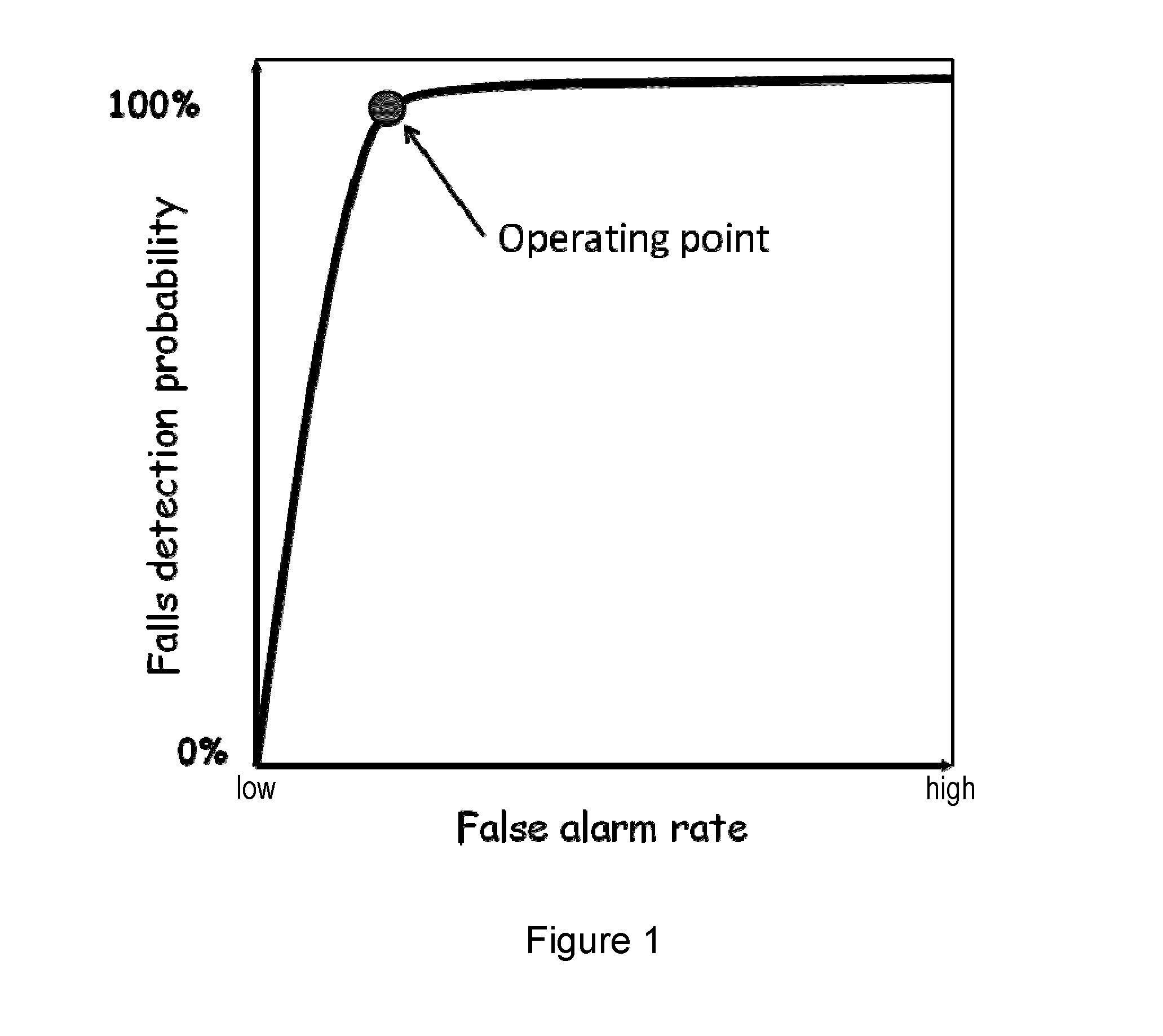
It will be appreciated from the above discussion that it is not possible to configure the fall detection algorithm to operate at an optimum point on the ROC curve for all users and in all situations.
In these cases it is accepted that this adapted setting also increases the probability of false alarms occurring, since the aim is to ensure that no falls are missed.

Method used


Image

  • Fall detection system and method
  • Fall detection system and method
  • Fall detection system and method

Examples


Embodiment Construction

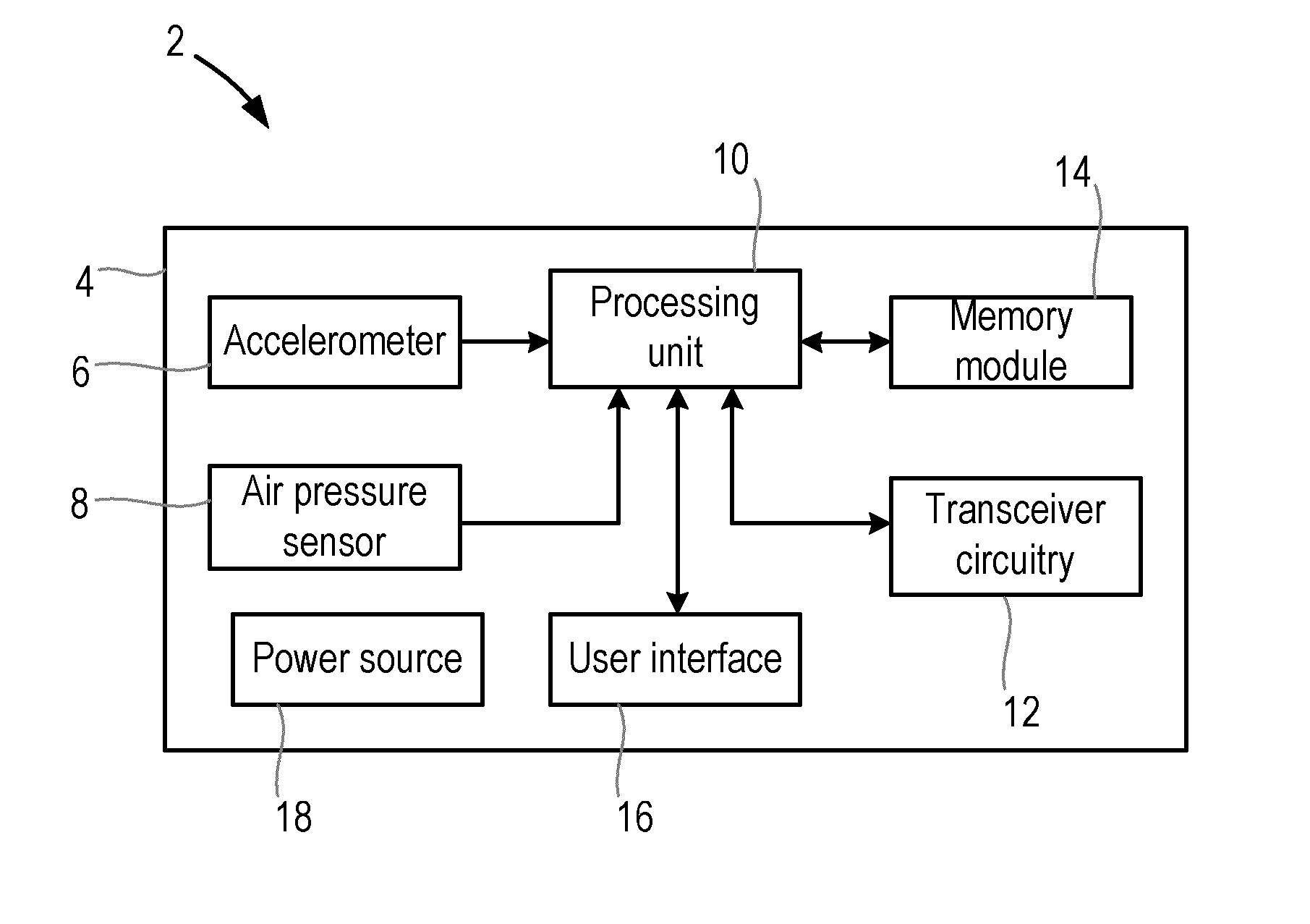
[0062]A fall detection system 2 according to an embodiment of the invention is shown in FIG. 5. In this embodiment of the invention, the fall detection system 2 comprises a user device 4 that is designed to be worn or carried by a user.

[0063]The user device 4 is preferably in the form of a pendant that is worn on a cord or chain around the user's neck, but it will be appreciated that the user device 4 is not limited to this form factor, and it is possible that the user device 4 could instead be designed to be worn at the user's wrist or waist, on their chest or back, or carried in their pocket.

[0064]The user device 4 comprises one or more movement sensors for obtaining measurements of the movements of the user. The one or more movement sensors 6, 8 typically includes at least an accelerometer 6 for measuring the accelerations experienced by the user, and in this exemplary embodiment, the user device 4 also comprises an air pressure sensor 8 that obtains measurements of air pressure ...


PUM


Abstract

There is provided a fall detection system for use in detecting falls by a user, the fall detection system comprising a processing unit configured to determine context information about the user and / or the environment in which the user is located, and to increase the sensitivity of a fall detection algorithm used to detect falls by a user in the event that the determined context information indicates that the user is or may be at an increased risk of falling, the increase in sensitivity occurring while the increased risk of falling is indicated by the determined context information.

Description

TECHNICAL FIELD OF THE INVENTION[0001]The invention relates to a fall detection system that is for detecting falls by a user.BACKGROUND TO THE INVENTION[0002]Falls affect millions of people each year and result in significant injuries, particularly among the elderly. In fact, it has been estimated that falls are one of the top three causes of death in elderly people. A fall is defined as a sudden, uncontrolled and unintentional downward displacement of the body to the ground, followed by an impact, after which the body stays down on the ground.[0003]A personal emergency response system (PERS) is a system in which help for a user can be assured. By means of Personal Help Buttons (PHBs) the user can push the button to summon help in an emergency. A majority of calls are because the user has fallen. Also, if the user suffers a severe fall (for example by which they get confused or even worse if they are knocked unconscious), the user might be unable to push the button, which might mean...

Claims


Application Information

Patent Timeline
IPC IPC(8): A61B5/11G01P13/00G08B21/04A61B5/00
CPCA61B2560/0223A61B2560/0242A61B5/1117A61B5/1118G08B21/043G01P13/00G08B29/185G08B29/20A61B2562/0219A61B5/7275G08B21/0446
Inventor ANNEGARN, JANNEKETEN KATE, WARNER RUDOPH THEOPHILEBALDUS, HERIBERT
Owner KONINKLJIJKE PHILIPS NV
Learn More