Injection Device for Selective Fixed or Variable Dosing

a fixed or variable dosing, injection device technology, applied in the direction of injection syringes, intravenous devices, automatic syringes, etc., can solve the problems of inability to read the physical small dose indication numerals, the surface useable for displaying the set dose is rather limited, and the fixed dose injection device becomes useless

Inactive Publication Date: 2016-08-04
NOVO NORDISK AS
View PDF3 Cites 22 Cited by
  • Summary
  • Abstract
  • Description
  • Claims
  • Application Information

AI Technical Summary

Benefits of technology

[0009]It is an object of the invention to eliminate or reduce at least one drawback of the prior art, or to provide a useful alternative thereto.

Problems solved by technology

While the above mentioned types of injection devices are quite suitable for delivery of various kinds of drugs according to various treatment plans they do possess obvious drawbacks.
In particular when it comes to all mechanical devices striving to be as small and handy as possible the surface useable for displaying the set dose is rather limited and visually impaired users often have trouble reading the physically small dose indicating numerals.
In regard to a fixed dose injection device even the most constant treatment regimens may need a dose adjustment at some point, e.g. during a dose titration period, in which case the fixed dose injection device becomes useless and another injection device adapted to deliver a dose of a different size is needed.
However, the user can only choose between a few predetermined fixed doses selected by the manufacturer, and the feature is therefore only suitable for a limited group of people.

Method used


Image

  • Injection Device for Selective Fixed or Variable Dosing
  • Injection Device for Selective Fixed or Variable Dosing
  • Injection Device for Selective Fixed or Variable Dosing

Examples


Embodiment Construction

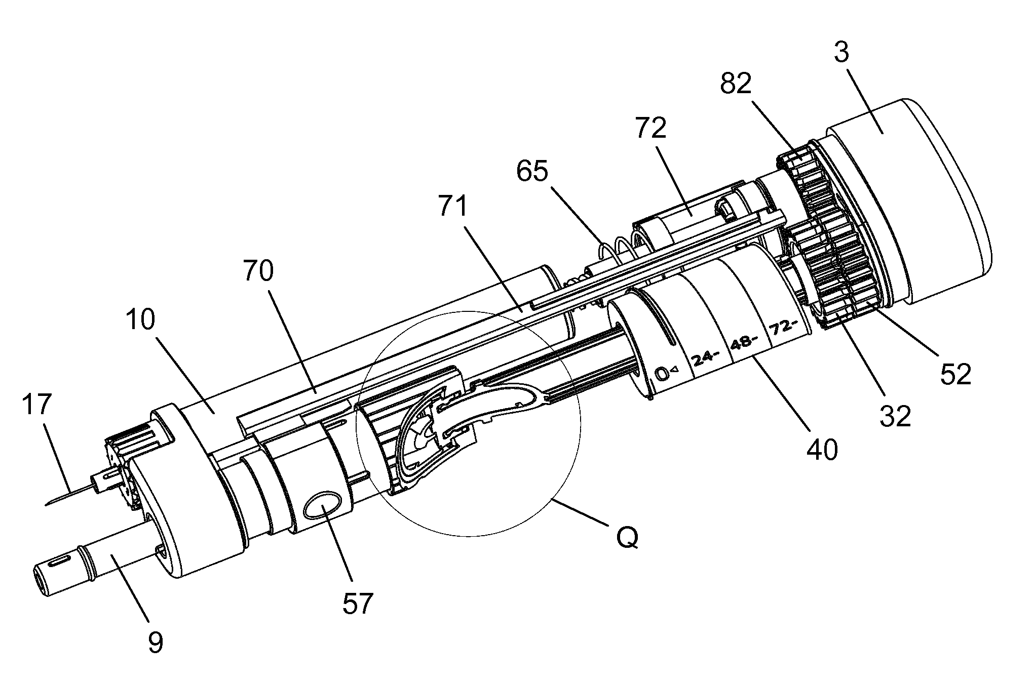
[0078]When in the following relative expressions, such as “upwards” and “downwards”, are used, these refer to the appended figures and not necessarily to an actual situation of use. The shown figures are schematic representations for which reason the configuration of the different structures as well as their relative dimensions are intended to serve illustrative purposes only.

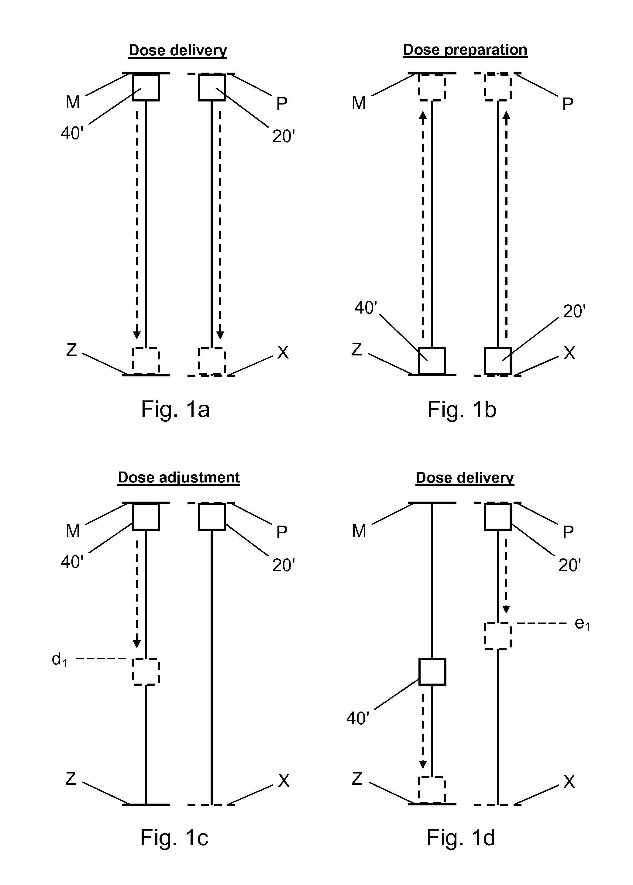
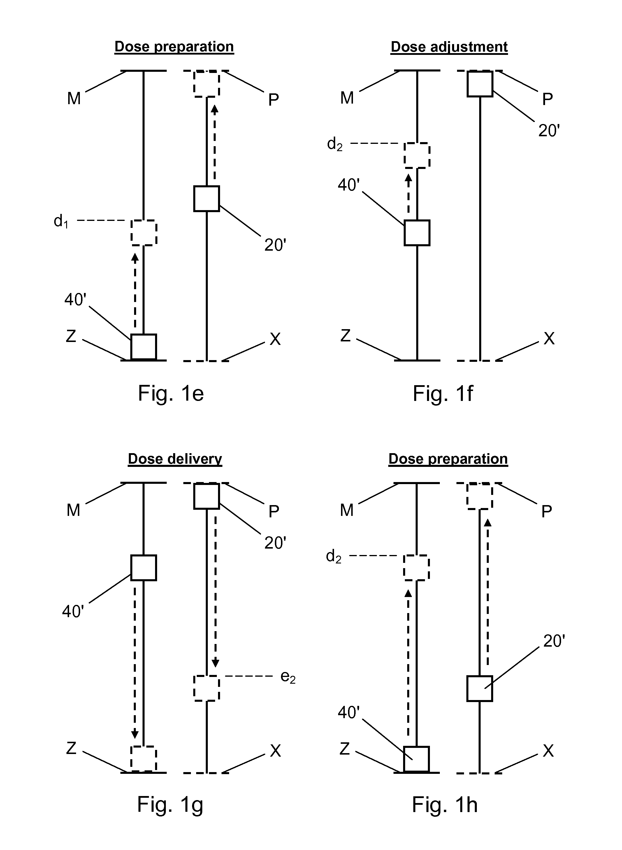
[0079]FIG. 1 is a simplified schematic representation of the principles underlying the present invention. FIGS. 1a through 1h illustrate the movement pattern of certain reciprocative drug delivery device elements during dose setting and dose delivery, respectively. The respective movements are to be understood as displacements relative to a base structure of the drug delivery device (not shown in FIG. 1), such as e.g. a drug delivery device housing. In the interest of clarity, the movements are shown as purely axial movements along straight lines, but it is noted that they could just as well be purely rotationa...


PUM


Abstract

A drug delivery device (1; 100; 200) comprising a housing (2; 102; 201, 202), a dose setting mechanism operable to set a dose to be delivered from a variable volume reservoir, and a dose delivery structure (60; 160; 260) activatable to expel a set dose. The dose setting mechanism comprises a dose indicating structure (40; 140; 240) for indicating a size of the set dose. The dose indicating structure (40; 140; 240) is coupled with the dose delivery structure (60; 160; 260) during expelling of the set dose and moved relative to the housing (2; 102; 201, 202) to a zero dose indicating position. The zero dose indicating position is a position which is fixed with respect to the housing (2; 102; 201, 202). The dose setting mechanism further comprises a dose setting structure (20; 120; 220) movable in a dose preparing direction relative to the housing (2; 102; 201, 202) to a dose prepared position to set a dose of a first size. The dose prepared position is a position along the dose preparing direction which is fixed with respect to the housing (2; 102; 201, 202). The dose setting structure (20; 120; 220) and the dose indicating structure (40; 140; 240) are coupled and configured to undergo first correlated displacements relative to the housing (2; 102; 201, 202) during movement of the dose indicating structure (40; 140; 240) to the zero dose indicating position and further coupled and configured to undergo second correlated displacements relative to the housing (2; 102; 201, 202) during movement of the dose setting structure (20; 20; 220) to the dose prepared position, where the first correlated displacements and the second correlated displacements are mutually reverse. Further, when the dose setting structure (20; 120; 220) is in the dose prepared position the dose indicating structure (40; 140; 240) is selectively displaceable relative to the housing (2; 102; 201, 202) while the dose setting structure (20; 120; 220) remains stationary in the dose preparing direction to allow adjustment of the dose of the first size and thereby setting of a dose of a second size.

Description

FIELD OF THE INVENTION[0001]The present invention relates to drug delivery devices, e.g. to power assisted drug delivery devices such as automatic injection devices. In particular, the invention relates to dose setting mechanisms for such delivery devices.BACKGROUND OF THE INVENTION[0002]Within some therapy areas the tendency of a patient to adhere to the prescribed therapy is dependent on the simplicity of the specific treatment regimen. For example, many people with type 2 diabetes are diagnosed with the disease at a relatively high age where they are less prone to accept a treatment that intervenes too much with their normal way of living. Most of these people do not like constantly being reminded of their disease and, as a consequence, they do not want to be entangled in complex treatment patterns or waste time on learning to operate cumbersome delivery systems.[0003]Basically, people with diabetes need to minimise their glucose excursions. Insulin is a well-known glucose loweri...

Claims


Application Information

Patent Timeline
Patent Type & Authority Applications(United States)
IPC IPC(8): A61M5/315
CPCA61M5/31541A61M2005/3126A61M5/24A61M5/31536A61M2005/3125A61M5/31578A61M5/3158A61M5/3202A61M2005/202A61M5/31551
Inventor ENGGAARD, CHRISTIAN PETERKIILERICH, EBBEPETERSEN, MICHAEL FRANKANDERSEN, MADS GROENLUND
Owner NOVO NORDISK AS
Why Eureka
Try Eureka