Glass forming apparatus

a glass forming and glass technology, applied in the direction of feeder spouts, etc., can solve the problems of molten glass leakage from the feeder, product and potential unacceptability, failure of the orifice ring to affect the glass, etc., and achieve the effect of reducing the variation in the size of the gob

Inactive Publication Date: 2016-08-04
PYROTECK INC
View PDF11 Cites 40 Cited by
  • Summary
  • Abstract
  • Description
  • Claims
  • Application Information

AI Technical Summary

Benefits of technology

[0006]The present disclosure is particularly directed to an improved orific...

Problems solved by technology

Failure of the orifice ring can affect the glass in several significant ways.
First, a fissure can score the surface of the glass and pass an imperfection on to the finished product.
Second, a faulty orifice ring can allow the molten glass to leak from the feeder.
Third, variation in gob weight delivere...

Method used


Image

  • Glass forming apparatus
  • Glass forming apparatus
  • Glass forming apparatus

Examples


Embodiment Construction

[0025]A typical orifice ring will be constructed of a high purity refractory composition of alumina-zirconia-silica such as Pyroguard Wearshield Z200 available from Pyrotek Inc. Of course, alternative refractory materials known to the skilled artisan are equally suitable for use in the present orifice ring construction.

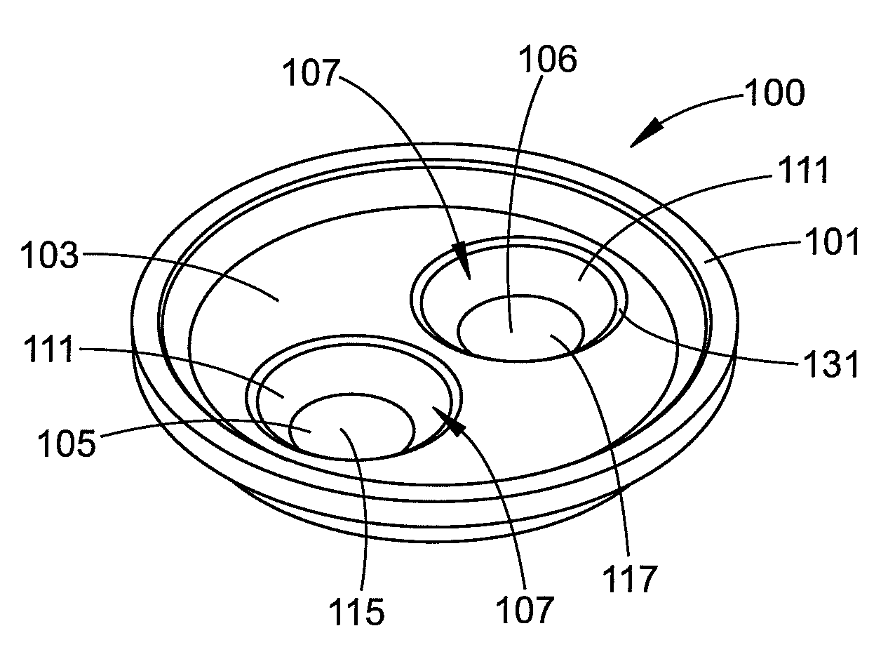
[0026]Referring now to FIGS. 4-10, the orifice ring 100 of the present disclosure includes an annular side wall 101 and a planar base wall 103. A pair of discharge holes 105 and 106 are formed in the base wall. It is noted that with respect to FIG. 4, the discharge holes have not yet been fully formed by drilling through the base wall 103.

[0027]Each of the discharge holes 105 and 106 can have a top opening 107 and a bottom opening 109. The top opening 107 is configured to be of a larger dimension than the bottom opening 109. In this regard, although the depicted discharge hole is circular at both the top and bottom opening, it is envisioned that different geometric co...


PUM


Abstract

According to a first embodiment, a refractory orifice ring of a glass forming apparatus is provided. The orifice ring includes an annular side wall and a base wall. At least one discharge hole is formed in the base wall. The discharge hole includes a top opening and a bottom opening, wherein the top opening has a surface area greater than a surface area of the bottom opening.

Description

[0001]This application claims the benefit of U.S. Provisional Application No. 62 / 111,777, filed Feb. 4, 2015, the disclosure of which is hereby incorporated by reference.BACKGROUND[0002]The present disclosure relates to feeders for delivering vertical runners of molten glass to a shear mechanism which severs the runners into discrete gobs for distribution to a glass container forming apparatus. The present disclosure more particularly relates to the refractory orifice ring for such apparatus which has one or a plurality of holes distributing a corresponding number of continuous runners of molten glass to the shear mechanism.[0003]Glass feeders are shown in U.S. Pat. Nos. 4,554,000 and 4,999,040, the disclosures of which are herein incorporated by reference. Such feeders have a spout bowl which has a cylindrical vertical outlet at the bottom. This cylindrical outlet is closed by a circular orifice plate which has one, two, three or four in-line holes through which the glass passes. P...

Claims


Application Information

Patent Timeline
IPC IPC(8): C03B7/088
CPCC03B7/088
Inventor RETORICK, RICKIE L.MARCH, TIMOTHY D.POKRZYK, JOHN A.PALMER, MARK
Owner PYROTECK INC
Why Eureka
Try Eureka