Damping valve

a technology of damping force and flange, which is applied in the direction of valve operating means/release devices, shock absorbers, mechanical devices, etc., can solve the problems of differential pressure in the gap with the flange, transference to a failure state, etc., and achieve the effect of avoiding uncontrollable damping for

Active Publication Date: 2016-08-04
KYB CORP
View PDF18 Cites 5 Cited by
  • Summary
  • Abstract
  • Description
  • Claims
  • Application Information

AI Technical Summary

Benefits of technology

[0011]It is an object of the present invention to provide a damping valve that is configured to avoid uncontrollability of the damping force when transferring to the fail state in the normal time.

Problems solved by technology

However, when the solenoid cannot be energized, the pilot valve retreats maximally from the valve seat disposed in the middle of the pilot passage to function as a switching valve obstructing the downstream of the valve seat in the pilot passage.
However, if the flow rate passing through the pilot valve from the upstream of the pilot passage increases, the differential pressure in the gap with the flange increases.
Accordingly, even in the normal time, this possibly causes a transference to a fail state where the switching valve closes.

Method used


Image

  • Damping valve
  • Damping valve
  • Damping valve

Examples


Embodiment Construction

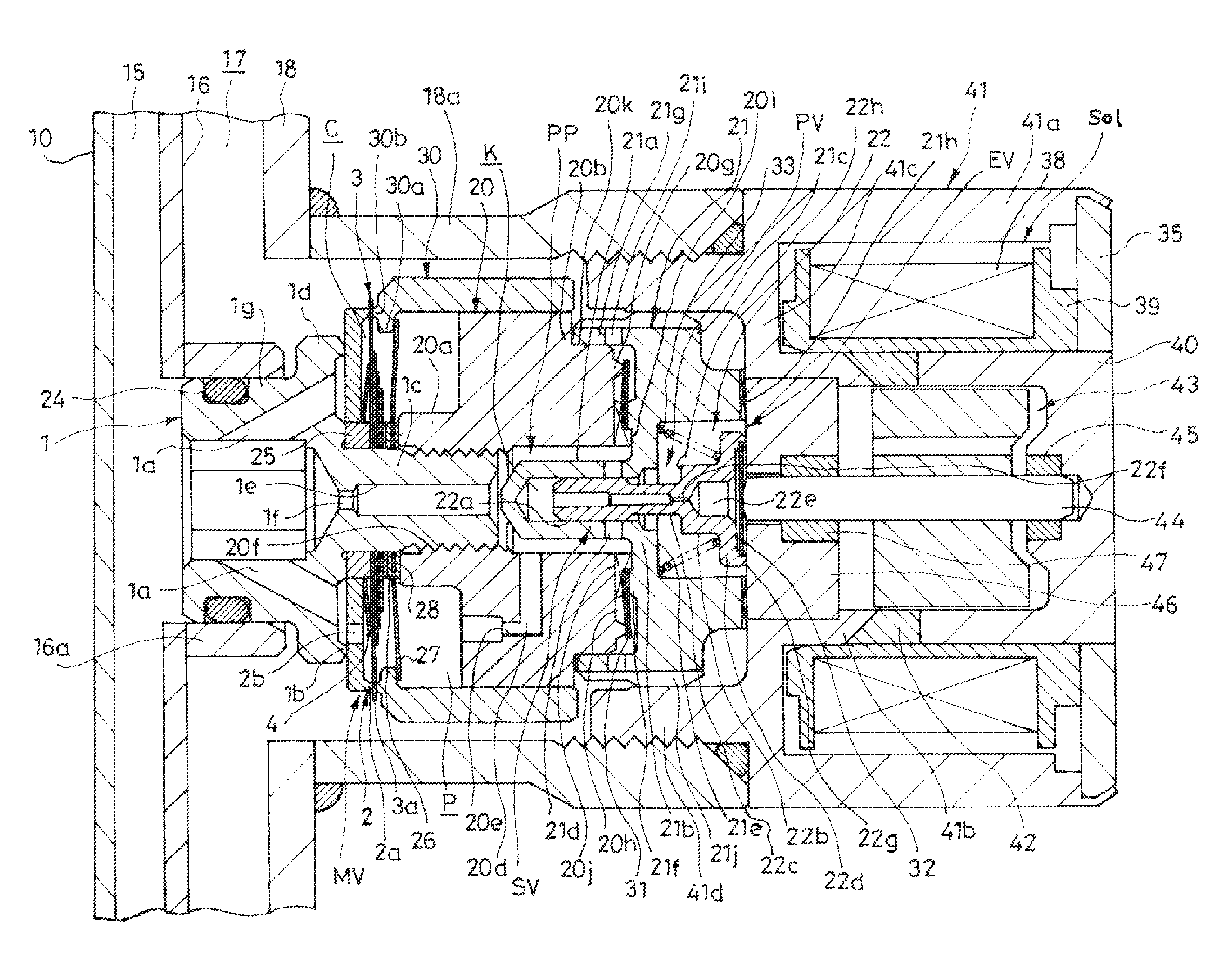
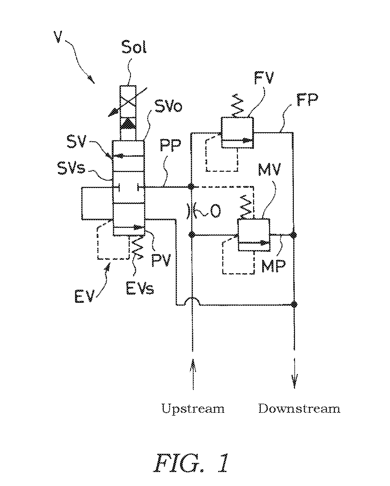
[0022]The following describes a damping valve V according to an embodiment of the present invention with reference to drawings.

[0023]As illustrated in FIG. 1, the damping valve V includes a main passage MP, a main valve MV, a pilot passage PP, an electromagnetic valve EV, a fail passage FP, and a fail valve FV. The main valve MV is disposed in the main passage MP to open and close the main passage MP. The pilot passage PP includes a throttle O, and reduces the pressure of the upstream in the main passage MP to guide as a back-pressure biasing the main valve MV to the closing direction. The electromagnetic valve EV includes a pressure control valve PV and a switching valve SV, and is controlled by a single solenoid Sol. The pressure control valve PV is disposed on the downstream of the throttle O in the pilot passage PP to control the back-pressure. The switching valve SV is disposed integrally with the pressure control valve PV to open and close the pilot passage PP. The fail passag...


PUM


Abstract

A damping valve includes a main valve opening and closing a main passage, and a pilot passage reducing a pressure of the upstream of the main passage by a throttle to guide as a back-pressure biasing the main valve to the closing direction. A pressure control valve being disposed on the downstream of the throttle and including a seating portion controlling the back-pressure, and a switching valve including a circular depressed portion opening and closing the pilot passage are integrated and controlled by a single solenoid. The damping valve includes fail passages being branched from the downstream of the throttle to bypass the main valve, and a fail valve opening and closing the fail passage. The switching valve is arranged on the upstream of the pressure control valve in the pilot passage. The fail passages are branched from the upstream of the switching valve of the pilot passage.

Description

TECHNICAL FIELD[0001]The present invention relates to a damping valve.BACKGROUND ART[0002]As a damping valve, there has been a variable damping valve that makes a damping force of a shock absorber, which is interposed between a vehicle body and axle shafts in a vehicle, variable. As this damping valve, for example, the applicant of the present application has been proposed a damping valve that includes a valve seat member, a main valve element, a pilot passage, an orifice, a spool, a valve housing, a pilot valve, and a solenoid. The valve seat member includes a port passing through from a cylinder to a reservoir and an annular valve seat surrounding the port. The main valve element is laminated on the valve seat member, and is seated on and separated from this annular valve seat to open and close the port. The pilot passage is branched from the upstream of the port. The orifice is disposed on the middle of the pilot passage. The spool has a tubular shape, and is in contact with the ...

Claims


Application Information

Patent Timeline
Patent Type & Authority Applications(United States)
IPC IPC(8): F16F9/34F16K31/06
CPCF16F9/34F16K31/06F16F9/50F16F9/46F16F9/187F16F2230/24
Inventor HAGIDAIRA, SHINICHIKOBAYASHI, YOSHIFUMI
Owner KYB CORP
Why Eureka
Try Eureka