
Automatic heat sleeving assembly machine

A set of automatic technology, applied in the direction of metal processing, metal processing equipment, manufacturing tools, etc., can solve the problems of the uniform temperature of the difficult workpiece A station, the difficulty of unifying the depth of knocking, and the complexity of personnel management, so as to avoid resources Waste and safety hazards, increased yield and uniformity, improved automation effectiveness

Inactive Publication Date: 2016-05-04
HANGZHOU HUANJIE AUTOMATION EQUIP
View PDF6 Cites 6 Cited by
  • Summary
  • Abstract
  • Description
  • Claims
  • Application Information

AI Technical Summary

Problems solved by technology

However, this type of indirect heating requires a lot of energy to establish a relatively high temperature zone, but only a small part of the heat can be transferred to the workpiece A station, resulting in a large degree of energy waste
At the same time, there are many potential safety hazards in the use of fire and electricity.
[0004] Secondly, manual heating is extremely difficult to maintain the uniformity of the individual temperature of each workpiece A station; when the workpiece B station is manually knocked into the workpiece A station, the depth of the knock-in is difficult to be uniform
[0005] The combination of the two problems resulted in a series of problems such as low product qualification rate, slow production speed, cumbersome process, certain dangers, high requirements for technical personnel, and complicated personnel management, which limited the production of products to a certain extent.

Method used


Image

  • Automatic heat sleeving assembly machine
  • Automatic heat sleeving assembly machine

Examples


Embodiment Construction

[0021] The present invention will be further described in detail with reference to the accompanying drawings and embodiments. The following embodiments are for explaining the present invention and the present invention is not limited to the following embodiments.

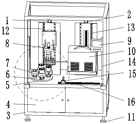
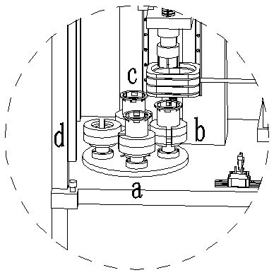
[0022] See figure 1 , This embodiment includes electrical systems, mechanical systems, and PLC control systems. The electrical system includes tooling servo system 1, heating servo system 2 and moving parts control system, and the electrical system is controlled by the PLC control system. The mechanical system includes a rack 3 and a built-in control cabinet 4 installed on the rack, a tooling dividing device, a touch device 9 and a high-frequency induction heating device 10.

[0023] The frame 3 is composed of square tubes and steel plates, and has a firm structure. The bottom of the rack 3 is provided with a leveling foot 11, and the height of the rack 3 can be fine-adjusted by the leveling foot 11 to meet actual usage...


PUM


Abstract

The invention relates to an automatic heat sleeving assembly machine and belongs to the field of machining equipment. The automatic heat sleeving assembly machine comprises an electrical system, a mechanical system and a programmable logic controller (PLC) control system. The electrical system comprises a tool servo system, a heating servo system and a moving part control system and is controlled by the PLC control system. The mechanical system comprises a machine frame, a built-in control cabinet, a tool dividing device, a touch device and a high-frequency induction heating device, wherein the built-in control cabinet, the tool dividing device, the touch device and the high-frequency induction heating device are installed on the machine frame. The automatic heat sleeving tooling process is completed through the cooperation of the electrical system, the mechanical system and the PLC control system. According to the automatic heat sleeving assembly machine, high-frequency induction heating is adopted, so that resource waste and potential safety hazards caused by indirect heating are avoided; in addition, the automation degree of the whole tooling process is greatly improved, the qualified rate of products and the production efficiency are also improved, and labor consumption is reduced.

Description

Technical field [0001] The invention relates to an automatic thermal sleeve assembling machine, which belongs to the field of mechanical processing equipment. Background technique [0002] In the field of production and processing, there are many product assembly processes in which the workpiece A station is heated and then the workpiece B station is pressed into the workpiece A station. The manual assembly is mainly performed by workers, that is, the workpiece A station is manually heated, and the workpiece is then used Knock into the workpiece A in the B station. [0003] Generally, when people heat objects, one is to use coal, oil, gas and other energy sources to generate heat; the other is to use electrical appliances such as electric furnaces to convert electrical energy into heat. This heat can only be transferred to the work station A through heat transfer (heat conduction, heat convection, and heat radiation) to achieve the purpose of heating the object. Objects heated by...

Claims


Application Information

Patent Timeline
IPC IPC(8): B23P19/02B23P11/02
CPCB23P19/02B23P11/025
Inventor 钟卫
Owner HANGZHOU HUANJIE AUTOMATION EQUIP
Learn More