Control device for continuously variable transmission

a technology of control device and transmission, which is applied in the direction of gearing control, gearing elements, gearing, etc., can solve the problems of deterioration of vehicle drive feeling, transmission mechanism feeling, and driving force gap (or acceleration gap, g-drop) produced, so as to reduce the driving force gap. , the effect of reducing the driving force gap

Active Publication Date: 2016-08-04
JATCO LTD +1
View PDF0 Cites 9 Cited by
  • Summary
  • Abstract
  • Description
  • Claims
  • Application Information

AI Technical Summary

Benefits of technology

[0015]Thus, the reduction rate of the drive force gap and the returning rate of the drive force gap can be gentled. Thus, the sluggish feeling applied to a driver in vehicle acceleration can be eliminated and thus, the drive feeling can be improved.

Problems solved by technology

However, even when the above-mentioned coordinated speed change is carried out, there is a case in which a driving force gap (or acceleration gap, G-drop) produced at up-shifting of the auxiliary transmission mechanism is felt by a driver due to the driving condition of the vehicle.
When the driving force gap is of a type that is clearly felt by the driver, he or she would have a sluggish feeling (G-drop feeling) in acceleration thereby failing to have an intended acceleration feeling, which causes deterioration in vehicle drive feeling.
However, because the driving force gap is determined by the interstage ratio between the first speed and second speed of the auxiliary transmission mechanism, it is quite difficult to eliminate or minimize the driving force gap without making a big change to hardware construction and control logic.

Method used


Image

  • Control device for continuously variable transmission
  • Control device for continuously variable transmission
  • Control device for continuously variable transmission

Examples


Embodiment Construction

[0021]In the following, an embodiment of the present invention will be described with reference to the accompanying drawings. It is to be noted that the following embodiment is only an example and the applicants have no intention of excluding application of various modifications and techniques that are not shown in the following embodiment. It is further to be noted that various modifications of the following embodiment may be carried out within a scope of the present invention, selection is available as the need arises and suitable combinations are available.

[0022][1. Entire System Construction]

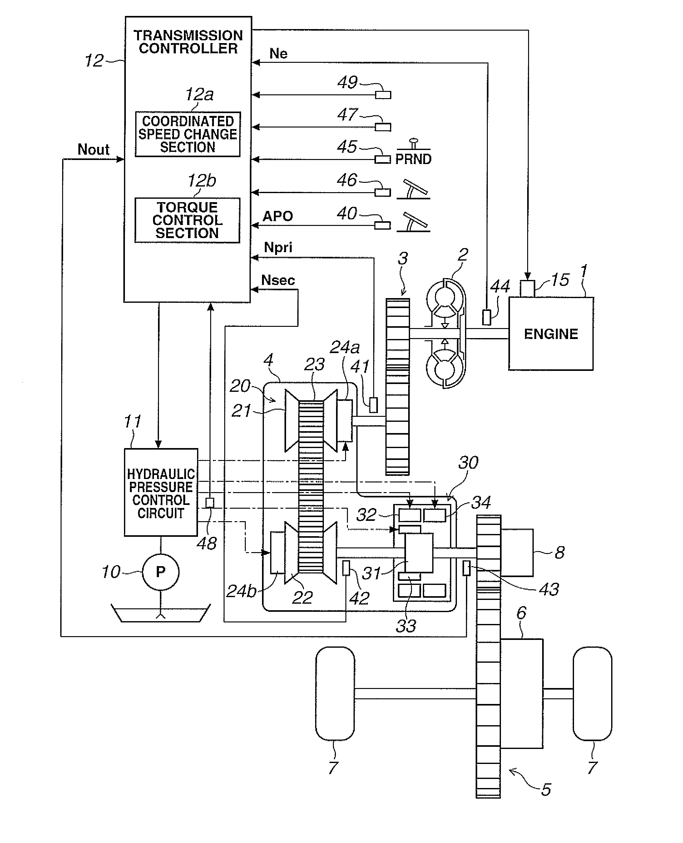
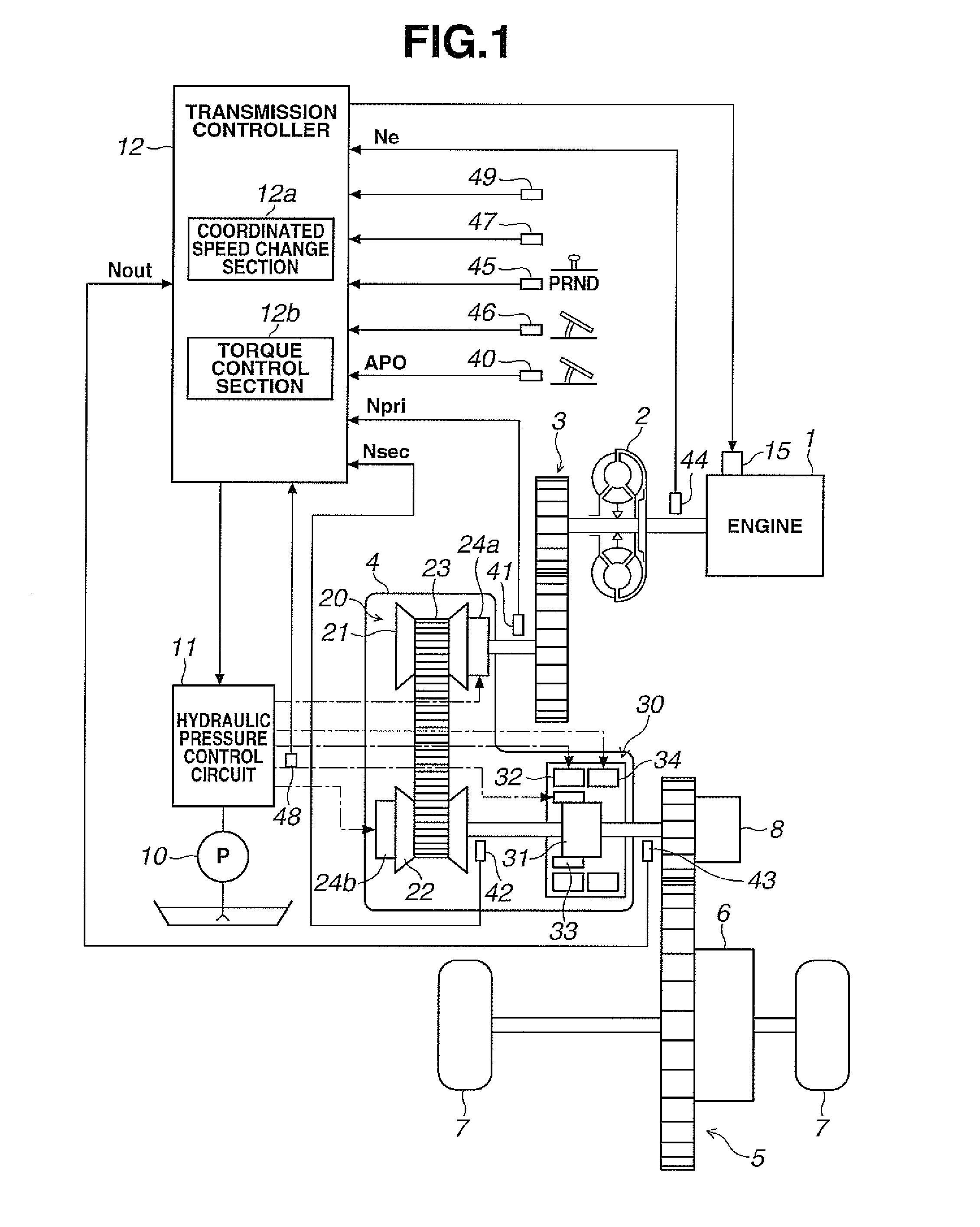
[0023]FIG. 1 is a schematic block diagram of a motor vehicle that has the control device for the continuously variable transmission of the embodiment mounted thereon. As is seen from FIG. 1, the vehicle is equipped with an engine (internal combustion engine) as a driving source. An output rotation of the engine 1 is transmitted to drive road wheels 7 through a torque converter 2 with a lock-...


PUM


Abstract

Disclosed is a control device for a continuously variable transmission (4) that has, as forward speed change stages, a first speed change stage (32) and a second speed change stage (33).The control device comprises a coordinated speed change means (12a) that carries out a coordinated speed changing in such a manner that when the speed change stage of an auxiliary transmission mechanism (30) is about to be changed, a speed change speed of the auxiliary transmission mechanism (30) is coordinated with a variator (20) and the variator (20) is controlled to carry out a speed change in a direction opposite to that of the auxiliary transmission mechanism (30) while carrying out the speed change operation of the auxiliary transmission mechanism (30), and a torque control means (12b) that carries out a torque regulating control during the coordinated speed changing under up-shifting by the coordinated speed change means, the torque regulating control being a control for effecting a torque-up operation to a driving source (1) after effecting a torque-down operation to the driving source and including a timing through which a starting time point of a drive force gap caused by the coordinated speed changing is advanced and a timing through which an ending time point of the drive force gap is delayed.

Description

TECHNICAL FIELD[0001]The present invention relates to a control device for a continuously variable transmission (which will be referred to as a CVT with an auxiliary transmission in the following) that is To equipped with both a belt type continuously variable transmission mechanism and a stepped variable transmission mechanism.BACKGROUND ART[0002]Hitherto, in a CVT with an auxiliary transmission, for effecting a speed change in the auxiliary transmission mechanism, a so-called coordinated speed change has been carried out wherein the continuously variable transmission mechanism (which will be referred to as a variator in the following) is speed-changed in a direction opposite to that of the auxiliary transmission mechanism, so that reduction of shift shock of the auxiliary transmission mechanism is obtained (which is disclosed in for example Patent Document-1 and Patent Document-2). In Patent Document-2, there is described a continuously variable transmission in which the speed cha...

Claims


Application Information

Patent Timeline
Patent Type & Authority Applications(United States)
IPC IPC(8): F16H61/70F16H37/02
CPCF16H61/04F16H61/662F16H37/021F16H61/70F16H2061/0492F16H63/50
Inventor TAKAHASHI, SEIICHIROINOUE, TAKUICHIROTAGAMI, KOUTAROUSHINOHARA, FUMITOSUZUKI, HIROYUKIOKAMOTO, YUJINOBUKAWA, TAKASHI
Owner JATCO LTD
Why Eureka
Try Eureka