Fuel injectors for gas turbine engines

a technology for gas turbine engines and fuel injectors, which is applied in the direction of burners, burner material specifications, burner manufacture, etc., can solve the problems of high temperature, corrosion environment, and component damage of such engines,

Active Publication Date: 2016-08-04
COLLINS ENGINE NOZZLES INC
View PDF2 Cites 23 Cited by
  • Summary
  • Abstract
  • Description
  • Claims
  • Application Information

AI Technical Summary

Benefits of technology

[0007]A fuel injector for a gas turbine engine includes a monolithic nozzle body that defines within its interior a fuel circuit. The fuel circuit includes an inlet, an outlet orifice, a main passage fluidly coupling the inlet with the outlet orifice, an

Problems solved by technology

Components within such engines can be subject to dynamic and

Method used


Image

  • Fuel injectors for gas turbine engines
  • Fuel injectors for gas turbine engines
  • Fuel injectors for gas turbine engines

Examples


Embodiment Construction

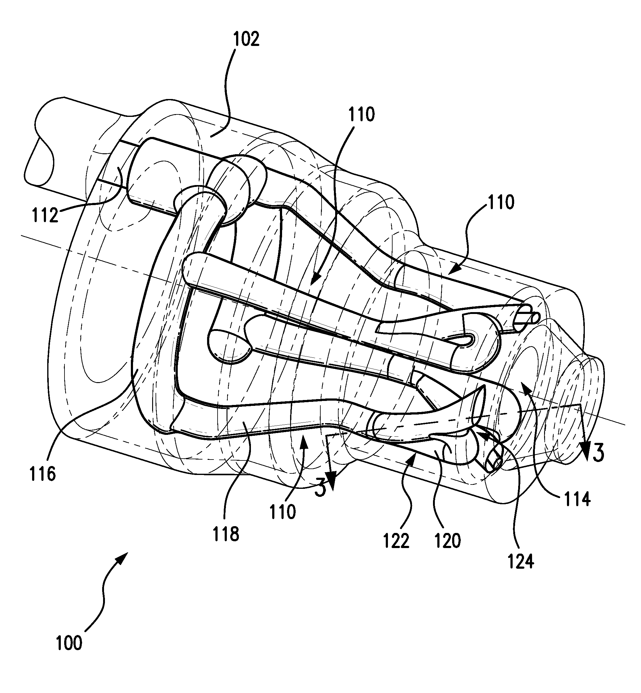
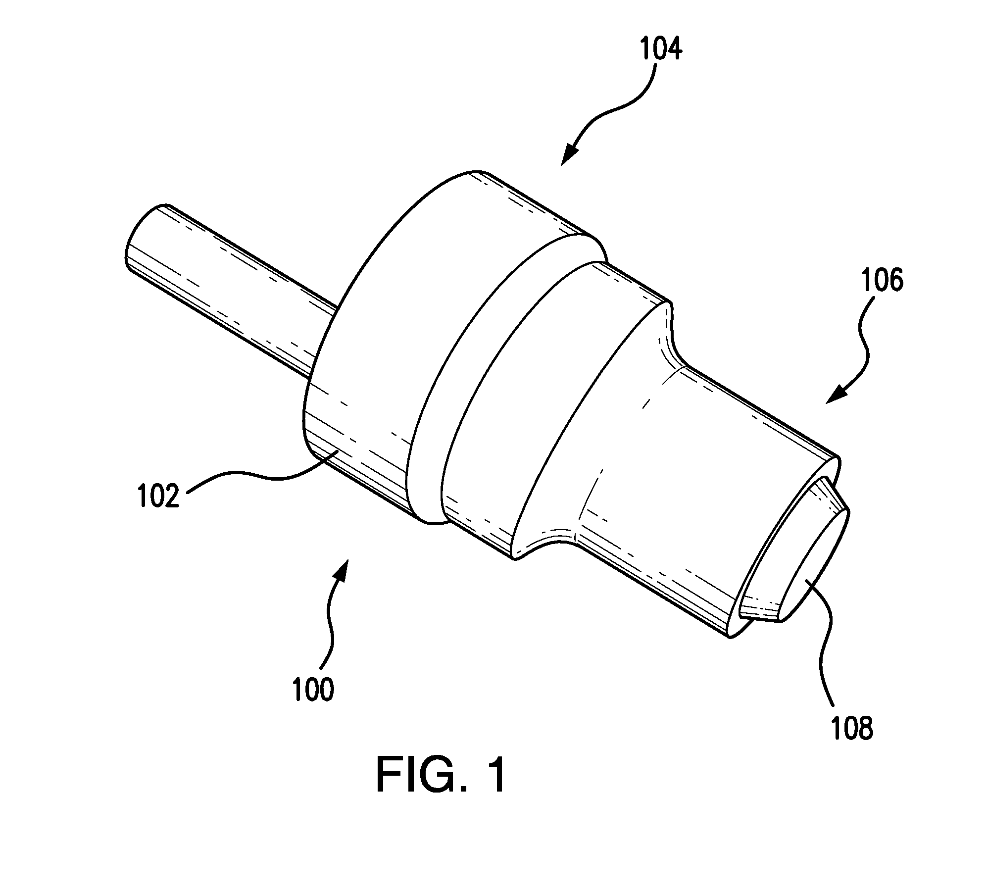
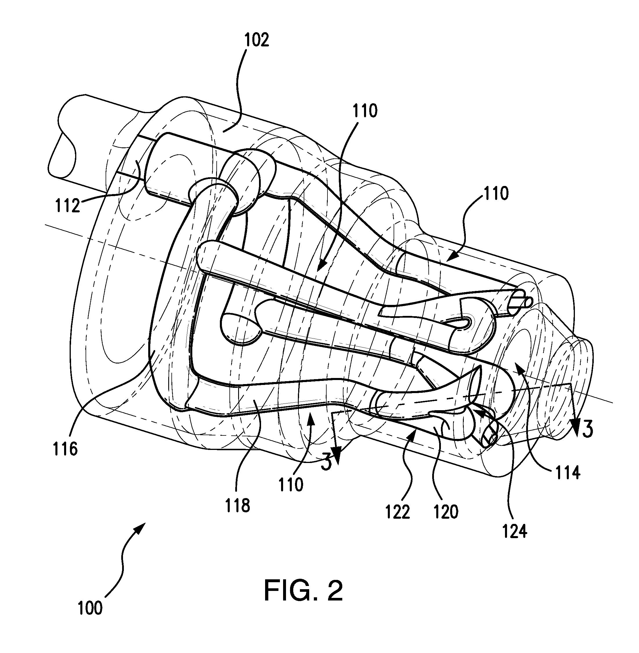
[0019]Reference will now be made to the drawings wherein like reference numerals identify similar structural features or aspects of the subject disclosure. For purposes of explanation and illustration, and not limitation, a partial view of an exemplary embodiment of a fuel injector in accordance with the disclosure is shown in FIG. 1 and is designated generally by reference character 100. Other embodiments of fuel injectors in accordance with the disclosure, or aspects thereof, are provided in FIGS. 2-4, as will be described. The systems and methods described herein can be used for gas turbine engine, such as in aircraft main engines or auxiliary power units.

[0020]As shown in FIG. 1, fuel injector 100 includes a nozzle body 102 that extends axially between an inlet end 104 and an opposed outlet end 106. Nozzle body 102 is a monolithic nozzle body formed using an additive manufacturing process and includes a prefilmer 108 circumferentially surrounding nozzle body 102. As illustrated ...


PUM


Abstract

A fuel injector for a gas turbine engine includes a monolithic nozzle body that defines within its interior one or more fuel circuits. Each fuel circuit includes an inlet, an outlet orifice, a main passage fluidly coupling the inlet with the outlet orifice, and a branch passage connected to the main passage. The branch passage connects to the main passage downstream of the inlet and upstream of the outlet orifice to form an effective metering flow area that is smaller than the flow area of the outlet orifice.

Description

BACKGROUND OF THE INVENTION[0001]1. Field of the Invention[0002]The subject invention relates to fuel injectors for gas turbine engines, and more particularly, to fuel injectors having additively manufactured nozzle bodies.[0003]2. Description of Related Art[0004]Gas turbine engines commonly include a compressor section in fluid communication with a turbine section through a combustion section. Components within such engines can be subject to dynamic and static loads, corrosive environments, and high temperatures. As gas turbine engines generally must satisfy high demands with respect to reliability, weight, performance, economic efficiency and durability, components are generally formed using a forging process or casting process, or by machining. Forging is commonly used for components subject to dynamic loading, such as compressor and turbine rotor blades. Investment casting is commonly used for static components subject to high temperatures, such as compressor and stator vanes an...

Claims


Application Information

Patent Timeline
IPC IPC(8): F23R3/28
CPCF23R3/28F23R3/286F23D11/10F23D11/24F23D11/38F23D2900/11101F23D2212/00F23D2212/203F23D2213/00F23D2900/00003F23D11/383B05B1/08B05B7/04B05B7/10
Inventor ZINK, GREGORY
Owner COLLINS ENGINE NOZZLES INC
Why Eureka
Try Eureka