Computer-assisted design method comprising a modelling step

a computer-aided design and step technology, applied in computing, instruments, electric digital data processing, etc., can solve the problems of not providing all the required properties of the construction tree, no simple way to satisfy the shape modification requirements, and the construction tree is lost, so as to achieve the effect of more robustness

Active Publication Date: 2016-08-04
INSTITUT NAT POLYTECHN DE GRENOBLE +1
View PDF6 Cites 5 Cited by
  • Summary
  • Abstract
  • Description
  • Claims
  • Application Information

AI Technical Summary

Benefits of technology

[0038]The idealization of the object M on the basis of its primitives confers more robustness on that process compared to the prior art for two reasons: firstly, each maximum primitive Pi and its connections determine as much the 3D location of the idealized representation of Pi as its connections with other neighboring idealized primitives, that is to say primitives whose Boolean intersection with Pi is non-zero. Secondly, a classification of the connection categories may be defined, which is important because the idealization processes still rely on the know-how of the user to process connections significantly different from the simple connections that CAD software or finite element calculation software currently process.

Problems solved by technology

Very often there is no simple way to satisfy the shape modification requirements because:the construction tree is lost if the geometrical model of the object has to be transferred between the software in which it was created and some other software meeting the requirement of some other discipline,the 3D object is described only by a single construction tree generated by the user during the construction of the object.
However, in numerous configurations such a construction tree does not provide all the required properties: modifications of dimensions, idealization process for finite element analysis, etc.
The best known CAD (computer-assisted design) and simulation software offer idealization functions that are not highly automated and not very robust.
They also offer decomposition into shape features and into primitives (basic cylinder, cone, cube, etc. shapes) that are limited to a single construction tree and are not very well suited to idealization because the primitives that they contain are often not suitable for idealization processes.

Method used


Image

  • Computer-assisted design method comprising a modelling step
  • Computer-assisted design method comprising a modelling step
  • Computer-assisted design method comprising a modelling step

Examples


Embodiment Construction

[0048]In the following sections, reference will often be made to the concepts and notation described next.

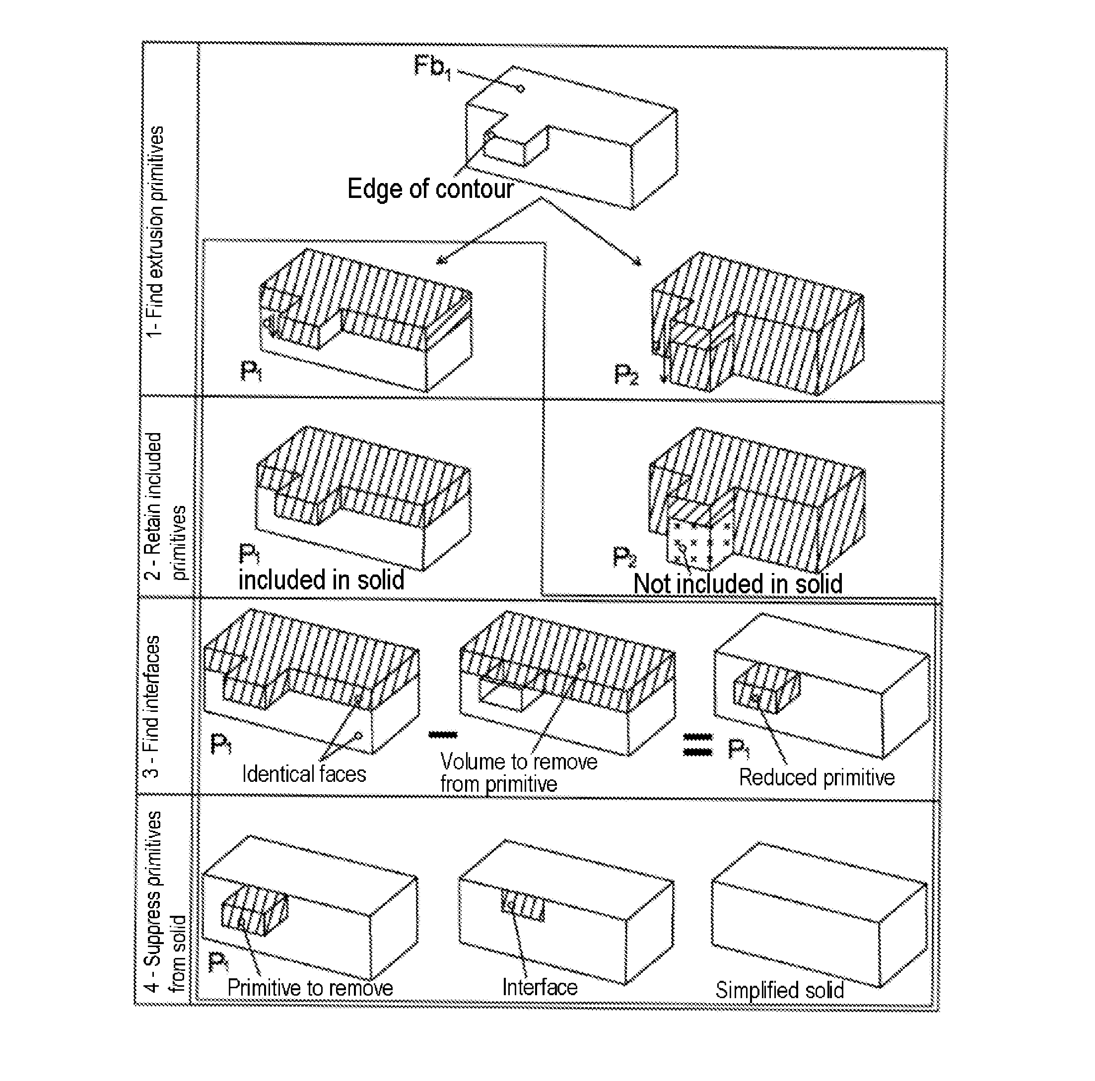
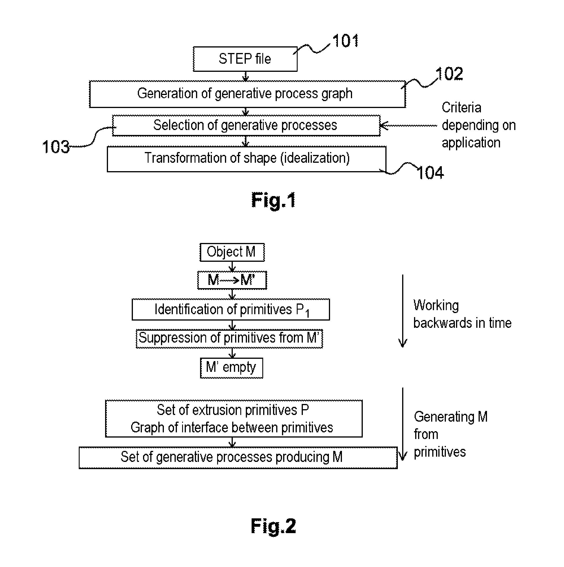
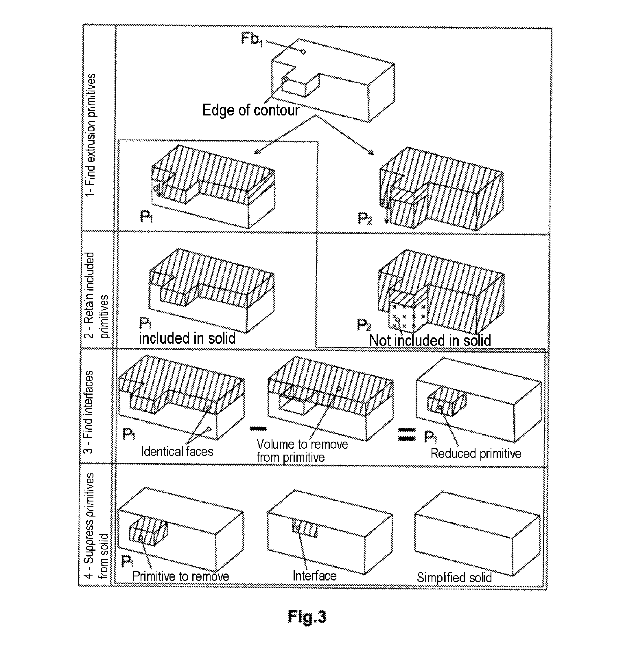
[0049]The 3D object construction graph generation process is determined on the basis of various construction sequences of that object. The description of the invention refers to an analogy between the geometrical construction of an object and a process including the temporal marks of the construction operations. To designate a construction operation, reference is therefore made to a time t characterizing the latter within a sequence describing a generative process. The preceding operation will therefore be labeled (t−1). The object for which the construction graph is to be determined is denoted M. This object is the result of combining the primitives contained in the construction graph. With reference to the times t of a sequence, there is also denoted by M0 the starting object M. There is denoted by M−j an evolution of the object M during a construction sequence the origin of w...


PUM


Abstract

A computer-assisted design method for a second three-dimensional object from a first three dimensional object known only by its boundary surfaces, through a surface model of the B-Rep type, of the planar, cylindrical, cone, sphere, or toroid type, excluding free forms in defining the boundary of the object. The first object is broken down into a set of simple volume primitives. The first object is associated with a construction graph defined from these volume primitives and a set of geometric parameters for using these volume primitives in the specific case of that first object. The construction graph enables a compact description of all of the construction alternatives of the object through Boolean combinations of these primitives. The second object is generated as an alternative of the first object according to that construction graph, by modifying some of these parameters.

Description

[0001]The present invention belongs to the field of methods of designing three-dimensional objects using a computer.[0002]It is directed in particular at a method of designing a three-dimensional object having volume and an association of that object with a construction graph based on simple shape primitives making it possible to describe in a compact manner all the construction variants of that same object. The automatic generation of the construction graph relies on a phase of decomposition of this initial 3D object, known only through a surface model of its boundary, into a set of simple volume primitives.PREAMBLE AND PRIOR ART[0003]During the design of a complete system, for example an aircraft, there may appear, for example by virtue of modifications of the specifications of the complete system, a requirement to modify geometrical characteristics of a known object, the geometric and mechanical characteristics of which are known.[0004]Such dimensional modification of a known thr...

Claims


Application Information

Patent Timeline
Patent Type & Authority Applications(United States)
IPC IPC(8): G06F17/50
CPCG06T17/10G06F17/50G06F30/00
Inventor BOUSSUGE, FLAVIENFINE, LIONELLEON, JEAN-CLAUDEHAHMANN, STEFANIE
Owner INSTITUT NAT POLYTECHN DE GRENOBLE
Why Eureka
Try Eureka