Method of estimating the fuel/air ratio in a cylinder of an internal-combustion engine by means of an extended Kalman filter

a technology of internal combustion engine and kalman filter, which is applied in the direction of electrical control, process and machine control, instruments, etc., can solve the problems of no robustness and the loss of efficiency of catalysts using nox traps in the course of time, and achieve the effect of more robustness

a technology of internal combustion engine and kalman filter, which is applied in the direction of electrical control, process and machine control, instruments, etc., can solve the problems of no robustness and the loss of efficiency of catalysts using nox traps in the course of time, and achieve the effect of more robustness

US7581535B2Inactive Publication Date: 2009-09-01INST FR DU PETROLE

Image

  • Method of estimating the fuel/air ratio in a cylinder of an internal-combustion engine by means of an extended Kalman filter
  • Method of estimating the fuel/air ratio in a cylinder of an internal-combustion engine by means of an extended Kalman filter
  • Method of estimating the fuel/air ratio in a cylinder of an internal-combustion engine by means of an extended Kalman filter

Examples


Embodiment Construction

Description of the Exhaust Process

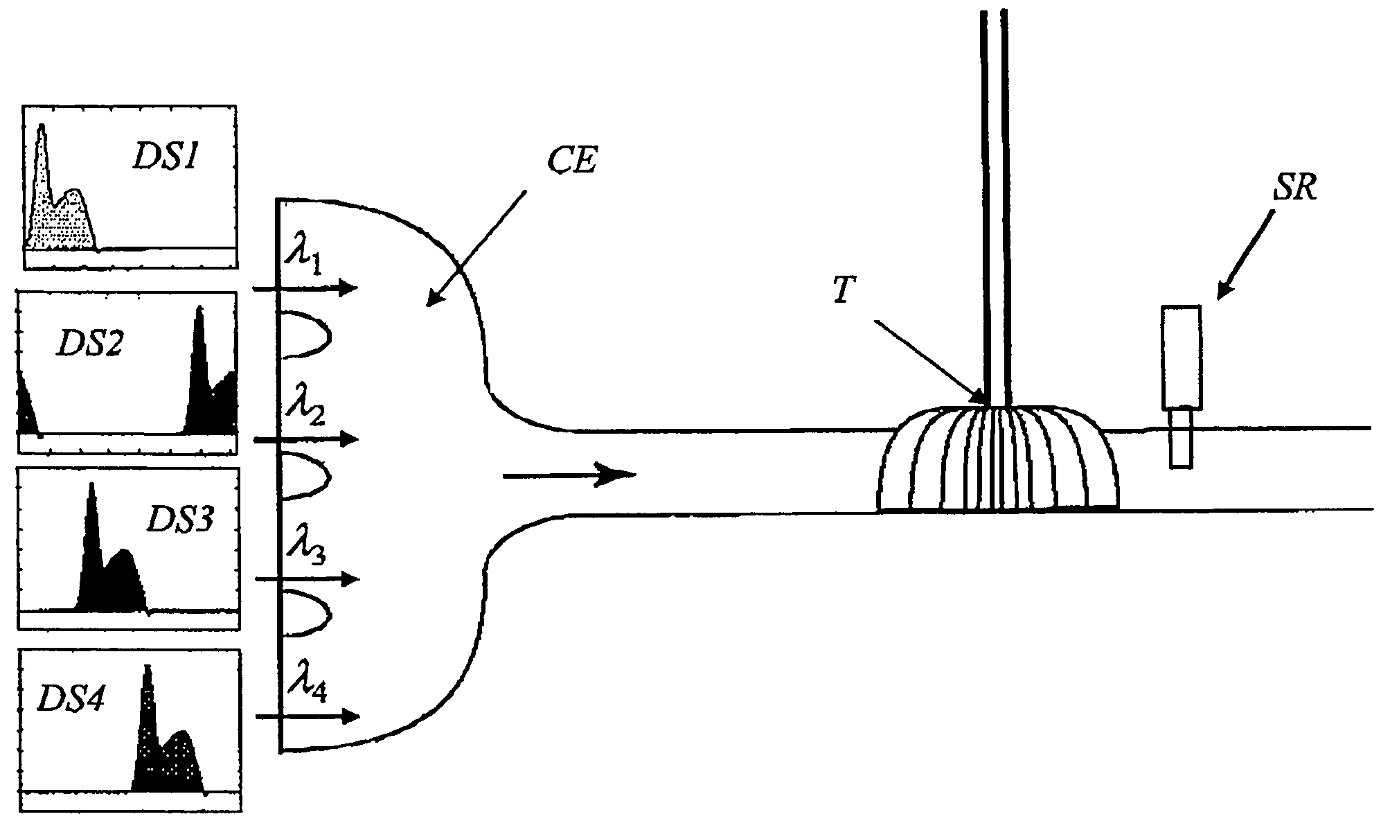
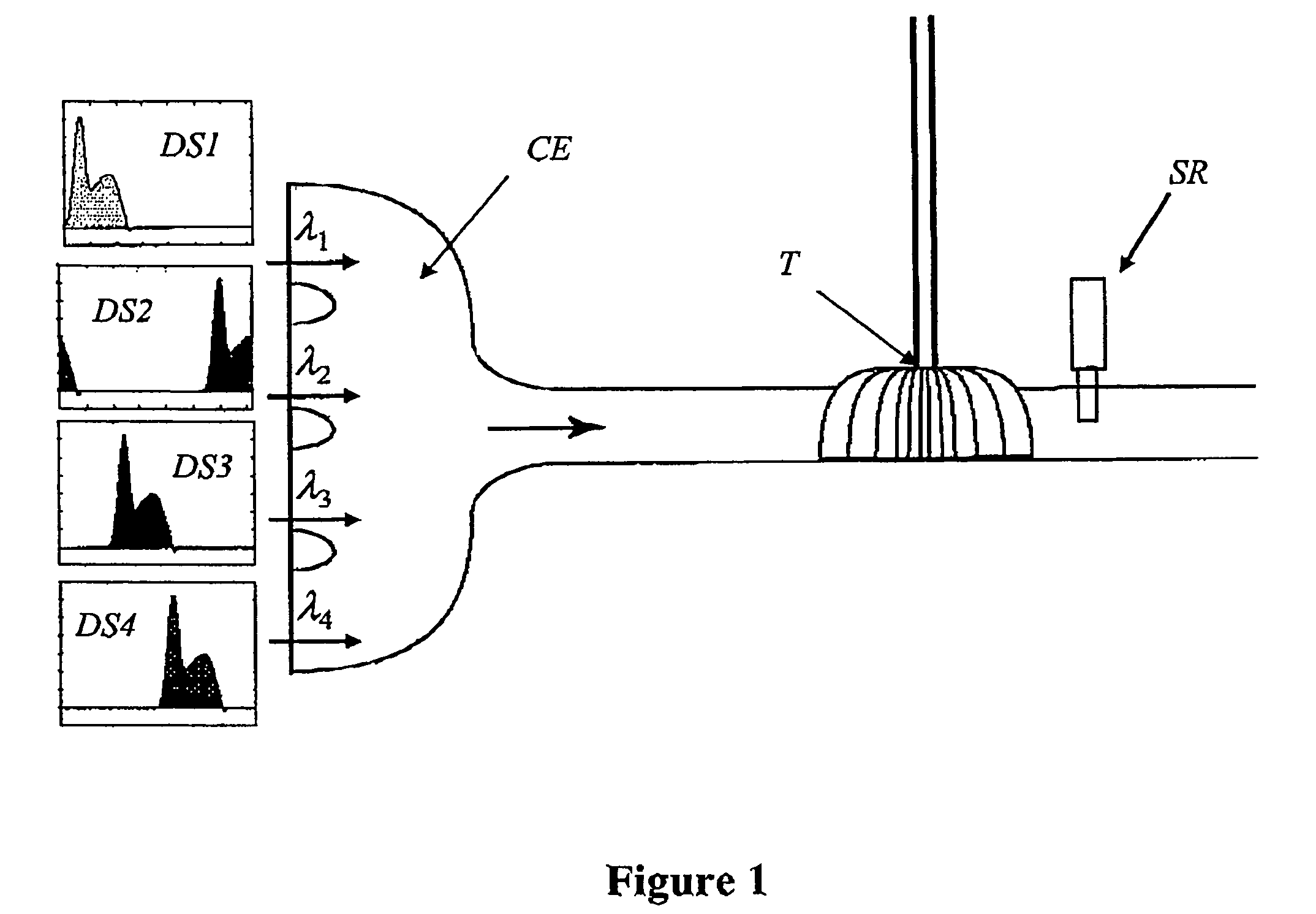
[0029]The exhaust process comprises the path traveled by the gases from the exhaust valve to the open air, at the exhaust muffler outlet. The engine in the present embodiment example is a 2200-cm3 4-cylinder engine. It is equipped with a variable-geometry turbo / supercharger. The diagram of FIG. 1 shows the descriptive elements of the exhaust process, wherein:

[0030]λ1 to λ4 are the fuel / air ratios in each one of the four cylinders,

[0031]SR is the fuel / air ratio probe,

[0032]CE corresponds to the exhaust manifold,

[0033]T corresponds to the turbine of the turbo / supercharger,

[0034]DS1 to DS4 represent the flow rates at the cylinder outlets.

[0035]Fuel / air ratio probe (SR) is arranged just after turbine (T). The gases, after combustion in the cylinder, undergo the following actions:

[0036]passage through the exhaust valve. The latter is controlled by a camshaft, with the lift law being bell-shaped. The flow rates will go from a high value, when the valve op...


PUM


Abstract

The present invention relates to a method of estimating the fuel / air ratio in each cylinder of an injection internal-combustion engine comprising an exhaust circuit on which a detector measures the fuel / air ratio of the exhaust gas. An estimator based on a Kalman filter is coupled with a physical model representing the expulsion of the gases from the cylinders and their travel in the exhaust circuit to the detector. The method has application to engine controls.

Description

CROSS REFERENCE TO RELATED APPLICATION[0001]Reference is made to commonly assigned related application Serial No. U.S. Ser. No. 11 / 437,702, filed in the U.S. Patent and Trademark Office on May 22, 2006, entitled “Method of Estimating the Fuel / Air Ratio in a Cylinder of an Internal Combustion Engine by Means of an Adaptive NonLinear FilterBACKGROUND OF THE INVENTION[0002]1. Field of the Invention[0003]The present invention relates to a method of estimating the fuel / air ratio of each cylinder of a fuel injected internal-combustion engine from a fuel / air ratio measurement downstream from the manifold and an extended Kalman filter.[0004]2. Description of the Prior Art[0005]Knowledge of the fuel / air ratio, characterized by the ratio of the mass of fuel to the mass of air, is important for all vehicles, whether equipped with gasoline engines, since it conditions good combustion of the mixture when it is close to 1, or with diesel engines, in which case the interest of knowing the fuel / air...

Claims


Application Information

Patent Timeline
01 Sep 2009
Publication
US7581535B2
IPC
F02D41/24; F01N3/00
CPC
F02D41/008; F02D41/1458; F02D41/1408; F02D41/1454; F02D2041/1431; F02D2041/1416; F02D2041/1417; F02D2041/143
Inventors
CHAUVIN, JONATHAN; MOULIN, PHILIPPE