Organic light emitting diode display

a light-emitting diode and display technology, applied in the direction of instruments, details of portable computers, semiconductor devices, etc., can solve the problems of difficult control of the electrostatic discharge (esd) generated in the touch panel and the display module, the heat generated in the display module driver ic, and the limited structure of the display module and the touch modul

a light-emitting diode and display technology, applied in the direction of instruments, details of portable computers, semiconductor devices, etc., can solve the problems of difficult control of the electrostatic discharge (esd) generated in the touch panel and the display module, the heat generated in the display module driver ic, and the limited structure of the display module and the touch modul

US20160225830A1Inactive Publication Date: 2016-08-04SAMSUNG DISPLAY CO LTD

Image

  • Organic light emitting diode display
  • Organic light emitting diode display
  • Organic light emitting diode display

Examples


Embodiment Construction

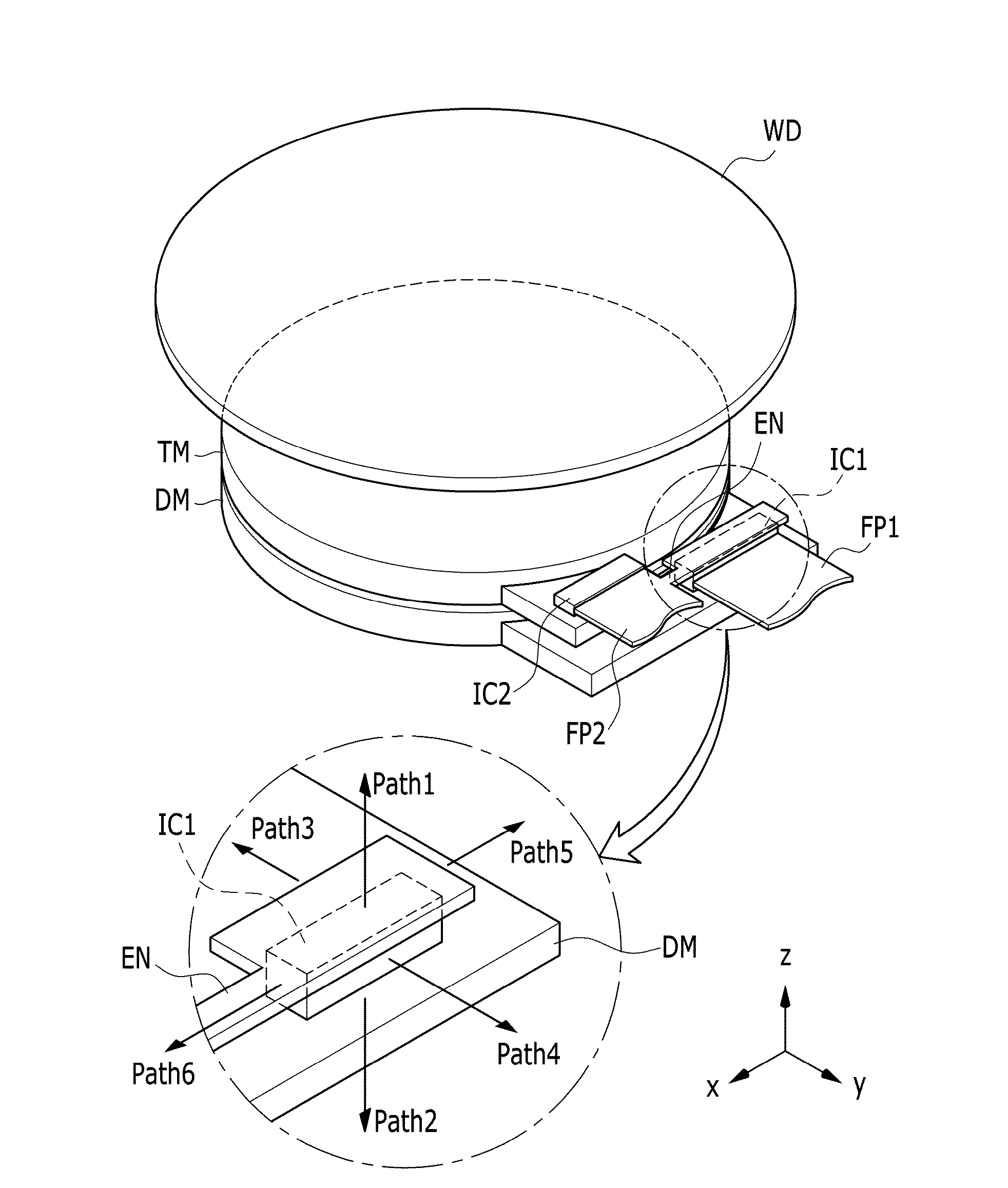
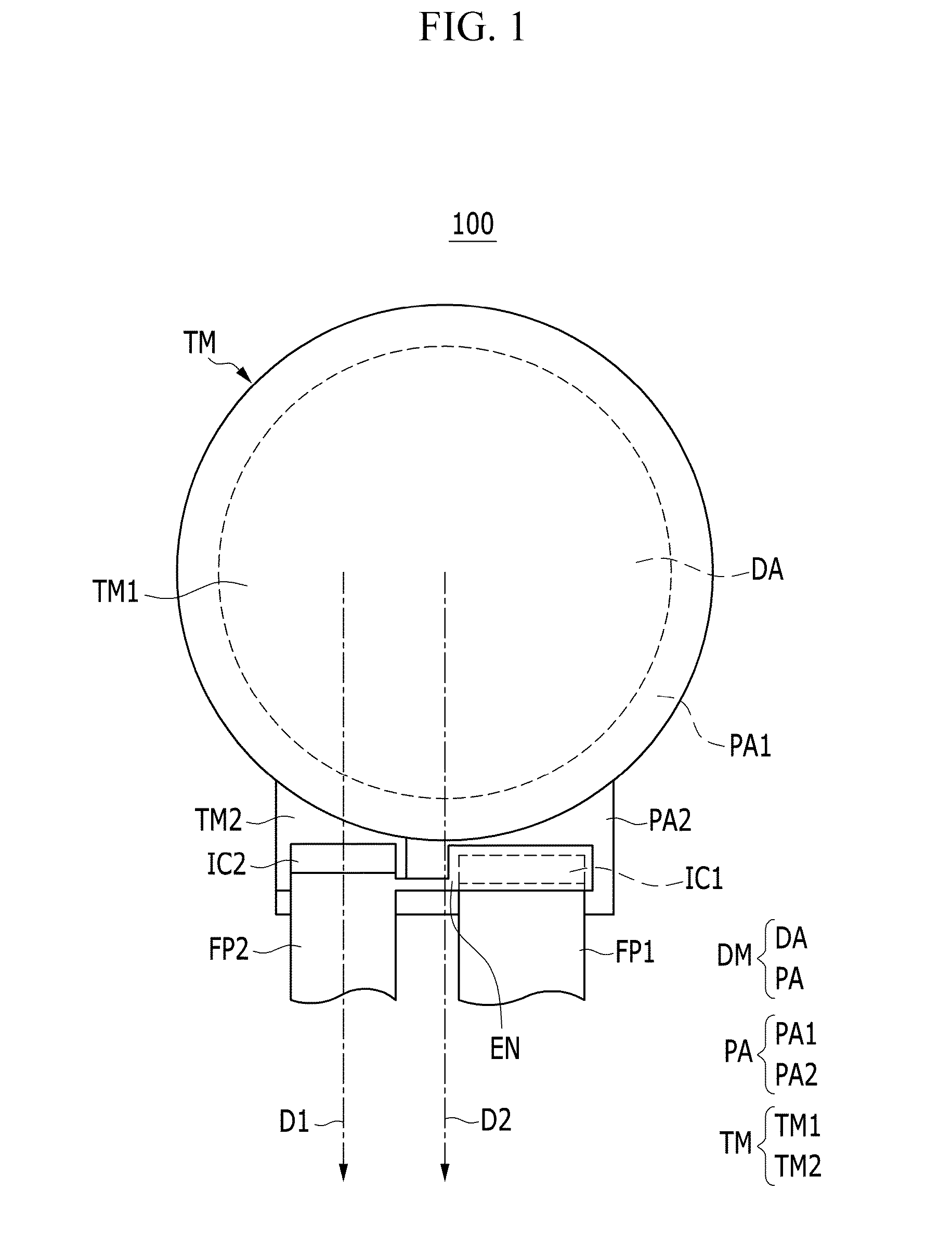
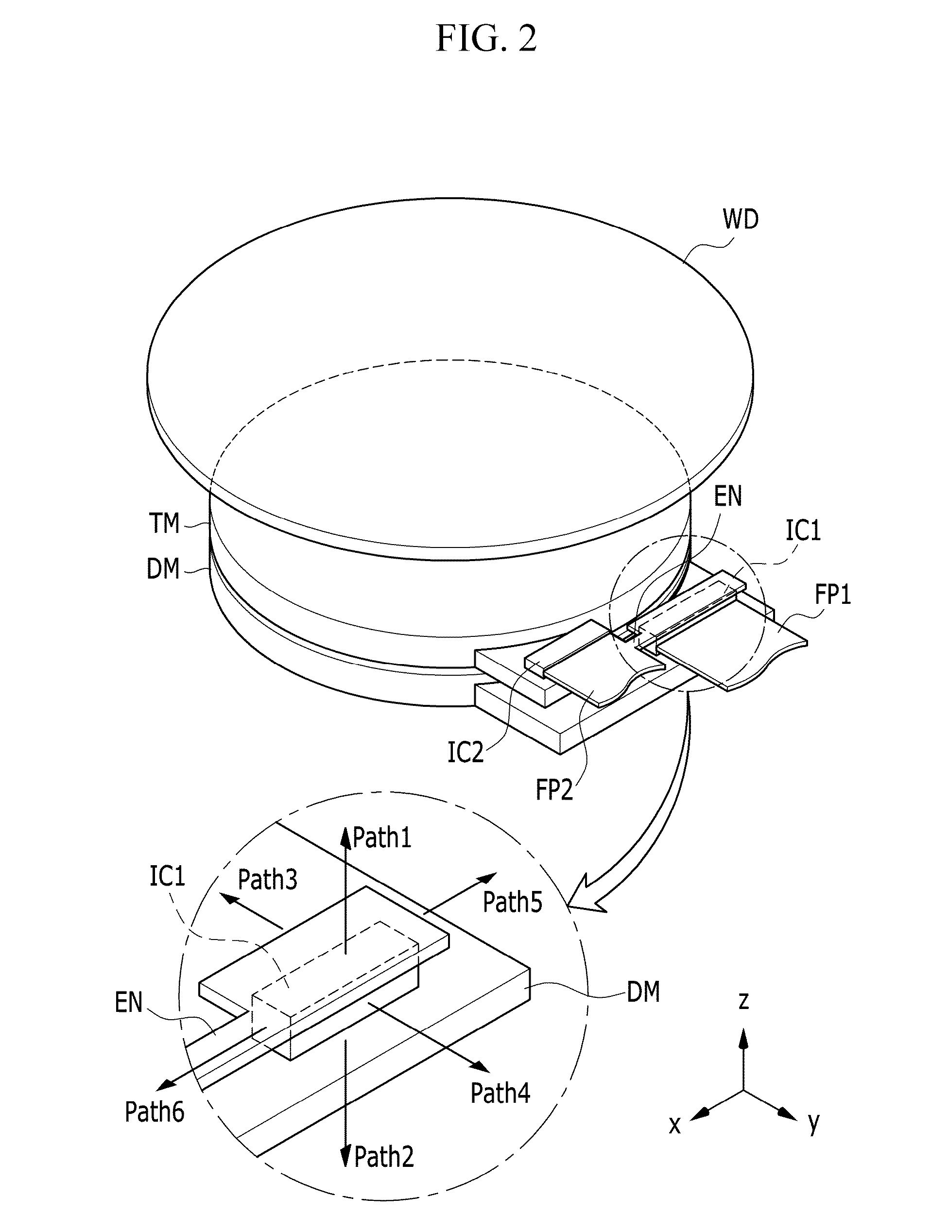
[0026]Hereinafter, example embodiments of the present invention will be described in some detail with reference to the accompanying drawings so as for those skilled in the art to carry out the present invention. As those skilled in the art would realize, the described embodiments may be modified in various different ways, all without departing from the spirit or scope of the described technology. The drawings and description are to be regarded as illustrative in nature and not restrictive. Like reference numerals designate like elements throughout the specification.

[0027]In addition, unless explicitly described to the contrary, the word ā€œcompriseā€ and variations such as ā€œcomprisesā€ or ā€œcomprising,ā€ will be understood to imply the inclusion of stated elements but not the exclusion of any other elements. Further, in the specification, when a part is connected to a configuration, the part may be not only physically directly connected, but also electrically connected to the configuratio...


PUM


Abstract

An organic light emitting diode display includes: display area where an image is not displayed, the non-display area including a first driver IC; a touch module above the display module and including a second driver IC; a first flexible printed circuit board (PCB) connected to the first driver IC; and a second flexible printed circuit board (PCB) connected to the second driver IC and including an extension configured to be in contact with the first driver IC.

Description

CROSS-REFERENCE TO RELATED APPLICATION[0001]This application claims priority to and the benefit of Korean Patent Application No. 10-2015-0016354, filed in the Korean Intellectual Property Office on Feb. 2, 2015, the entire content of which is incorporated herein by reference.BACKGROUND[0002]1. Field[0003]Aspects of embodiments of the present invention relate generally to an organic light emitting diode display.[0004]2. Description of the Related Art[0005]A display device is a device that displays an image. In recent years, an organic light emitting diode display has attracted attention.[0006]Organic light emitting diode displays have a self-emitting characteristic and may not require a separate light source, as opposed to liquid crystal display devices, which may include a separate light source. Therefore, the thickness and weight of organic light emitting diode displays may be reduced relative to other display devices such as liquid crystal display devices. Further, organic light e...

Claims


Application Information

Patent Timeline
04 Aug 2016
Publication
US20160225830A1
IPC
H01L27/32; G06F1/16; G06F3/041
CPC
H01L27/323; G06F3/0412; G06F2203/04102; G06F1/16; G06F3/0416; G06F1/163; G06F1/1656; G06F1/203
Inventors
JANG, NAM JIN