Power tool

Active Publication Date: 2016-08-04
MAKITA CORP
View PDF2 Cites 8 Cited by
  • Summary
  • Abstract
  • Description
  • Claims
  • Application Information

AI Technical Summary

Benefits of technology

[0059]In at least some aspects of the present teachings, air for cooling the motor can pass more easily through the inner side (interior) of the stator owing to the notched part(s) provided in the outer circumference of the sensor-circuit board, which makes it possible to cool the coils of

Problems solved by technology

Consequently a gap between the electrically insulating member and the sensor-circuit board is narrowed by the crossover wires, thereby restricting the flow path for the cooling air to pass through.
Therefore the coils cannot be effectively cooled

Method used


Image

  • Power tool
  • Power tool
  • Power tool

Examples


Example

[0084]Embodiments of the present teachings are explained below, with reference to the drawings.

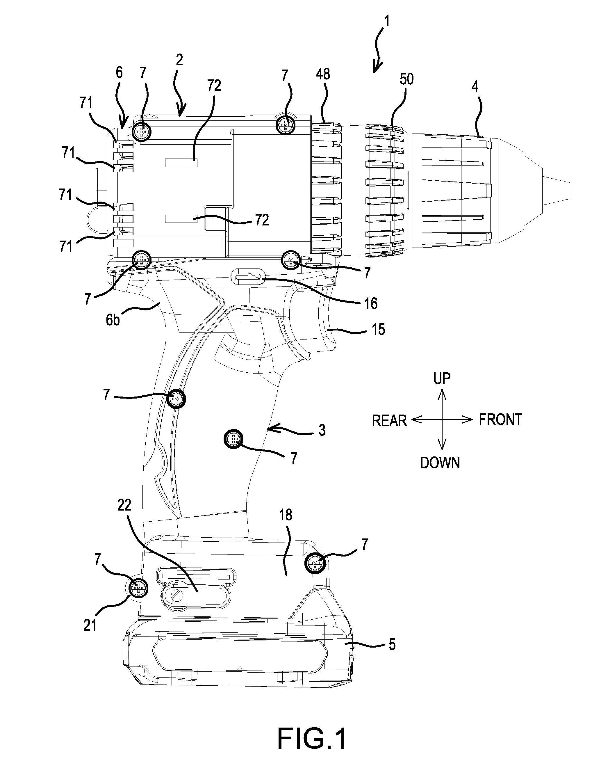
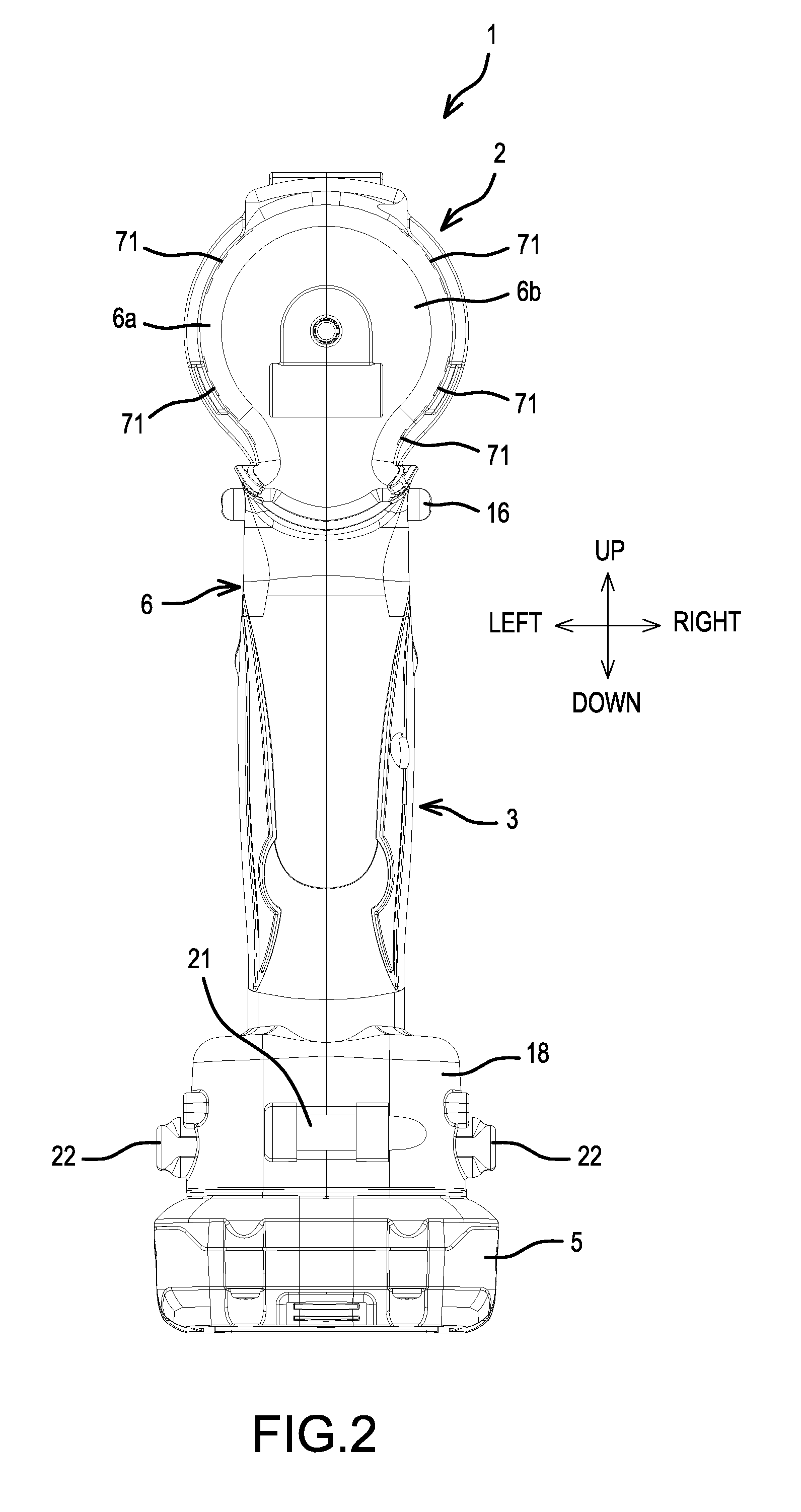
[0085]The hammer driver-drill 1 shown in FIGS. 1-4 includes a handle 3 that protrudes downward from a main body 2 that extends in a front-rear direction. A drill chuck 4 is configured or adapted to grasp at its tip a bit and is provided on a front end of the main body 2. A battery pack 5 serves as a power supply and is detachably mounted on a lower end of the handle 3. A housing 6 is formed by joining (assembling), using screws 7 extending in the left-right direction, left and right half housings 6a, 6b, which continuously form the handle 3 and a rear-half portion of the main body 2.

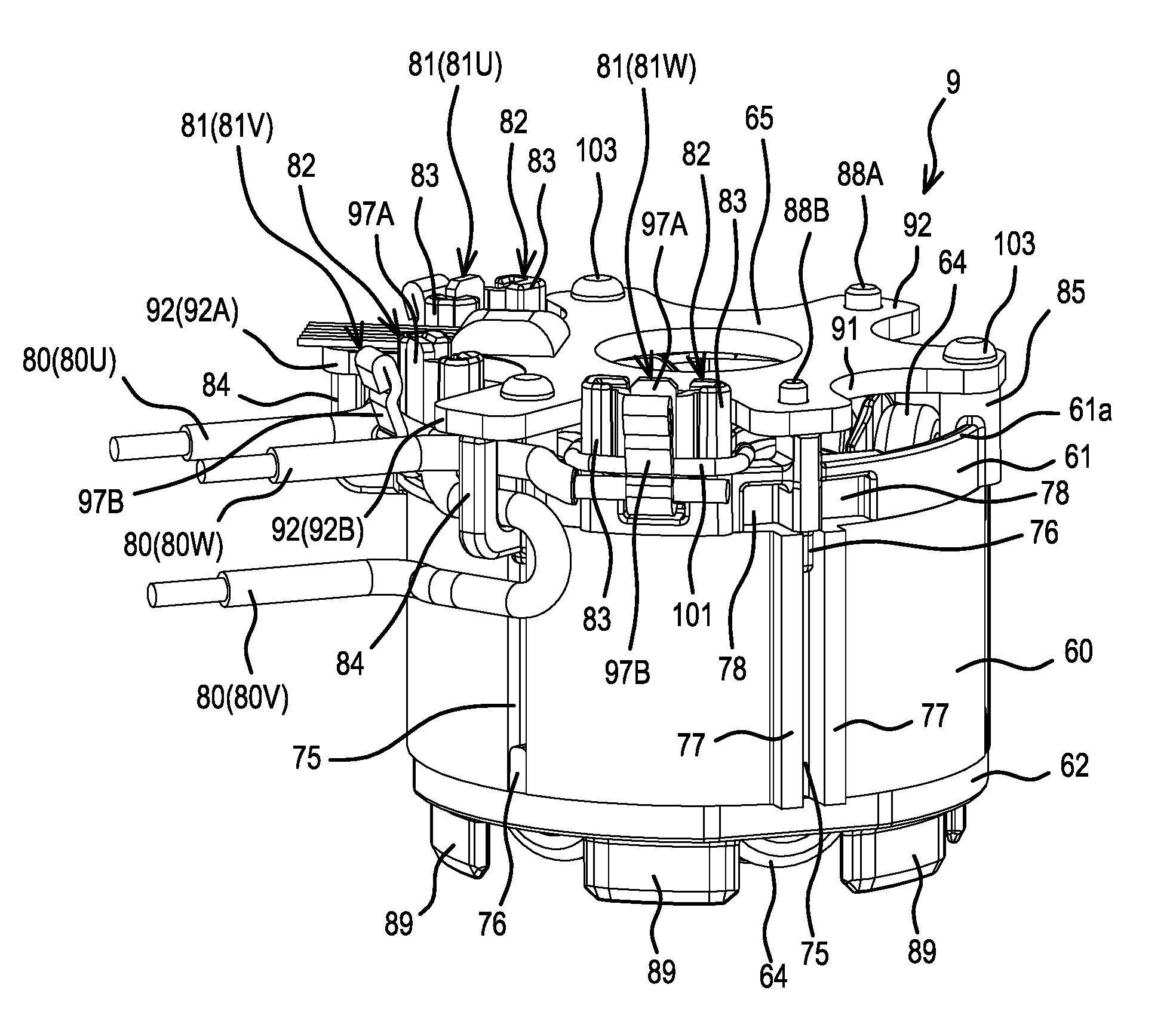
[0086]A rear portion within the main body 2 houses a tubular stator 9 and a rotor 10, which is disposed in an inner part (interior) of the stator 9. An inner-rotor type brushless motor 8 comprising a rotary shaft 11 is housed in the rotor 10. A gear assembly 12 comprises a spindle 13 that protrudes forward from...


PUM


Abstract

A power tool (1) includes a brushless motor (8) having a stator (9) and a rotor (10). The stator (9) includes: a tubular stator core (60); front and rear insulators (61, 62) fixed to the stator core; and coils (64), which are wound around a plurality of teeth (63) on the stator core. The rotor (10) includes: a rotor core (67) disposed within the stator; a rotary shaft (11) fixed to the rotor core; and one or more permanent magnets (68) fixed to the rotor core. A sensor-circuit board (65) detects the position(s) of the permanent magnet(s) and is fixed to the stator. One or more notched parts (91) is/are formed, in an outer circumference of the sensor-circuit board, between circumferentially-adjacent teeth in an axial direction of the stator. The notch part(s) allow(s) air for cooling the brushless motor to pass more easily through the interior of the stator.

Description

CROSS-REFERENCE[0001]The present application claims priority to Japanese patent application serial numbers 2015-020491 and 2015-020492, both filed on Feb. 4, 2015, the contents of which are incorporated fully herein by reference.TECHNICAL FIELD[0002]The present invention relates to a power tool, such as a driver drill, that employs a motor having a wound-type stator.BACKGROUND ART[0003]Some known power tools, such as driver drills, utilize a motor (e.g., a brushless motor) having a wound-type stator that serves as its drive source. If a brushless motor is employed, then, as disclosed in US 2013 / 270932, electrically insulating members are respectively fixed to opposite ends of a stator core, which is formed by laminating a plurality of steel plates and which has a plurality of teeth (e.g., six) that protrude from an inner side of the stator core. Coils of each phase (all coils collectively constituting a multiphase winding wire) are respectively wound around each pair of teeth, which...

Claims


Application Information

Patent Timeline
IPC IPC(8): H02K7/14H02K3/24H02K1/27H02K11/21H02K3/28
CPCH02K7/145H02K11/21H02K3/28H02K1/27H02K3/24H02K2211/03H02K5/08H02K5/225H02K9/02H02K2203/09H02K1/14B25F5/02H02K29/06H02K29/08H02K11/215
Inventor NIWA, AKIRAKOUDA, KEI
Owner MAKITA CORP
Why Eureka
Try Eureka