Projector device

Active Publication Date: 2007-02-01
SANYO ELECTRIC CO LTD
View PDF7 Cites 4 Cited by
  • Summary
  • Abstract
  • Description
  • Claims
  • Application Information

AI Technical Summary

Benefits of technology

[0021] Accordingly, it is possible to suppress to a minimum the pressure loss occurring when the air delivered from the cooling unit passes through each of the small holes 57 constituting the first air intake opening 53 and the second air intake opening 54, while preventing the broken pieces of the lamp 41 from flying outside the reflector 46 upon the explosion, by setting the opening a

Problems solved by technology

However, the above conventional lamp unit has a problem of the lamp being unable to be sufficiently

Method used


Image

  • Projector device
  • Projector device
  • Projector device

Examples


Example

[0036] The present invention embodied in a liquid crystal projector device will be specifically described below with reference to the drawings. In the description given below, the image projection direction of the liquid crystal projector device shown in FIG. 1 is defined as the forward direction, and right and left are defined by facing the front face of the liquid crystal projector device.

Overall Construction

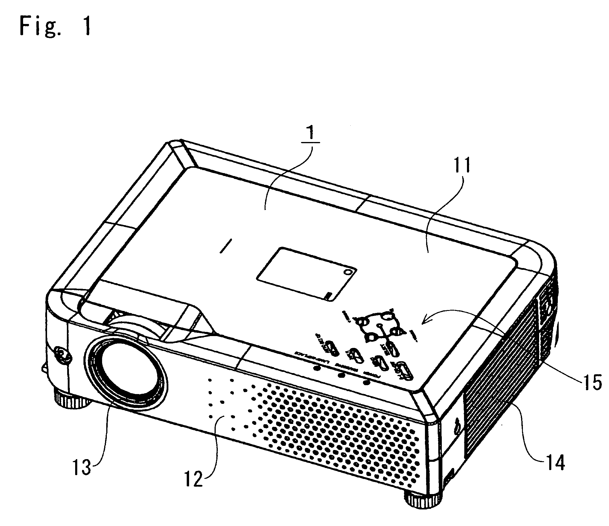
[0037] As shown in FIG. 1, the liquid crystal projector device of the present invention includes a flat casing 1 including a lower half case 12 and an upper half case 11. A manipulation portion 15 including a plurality of manipulation buttons is disposed on a surface of the casing 1, while a projection window 13 is provided on the front face of the casing 1. A vent 14 for discharging the air in the casing 1 to the outside is provided on the right side wall of the casing 1.

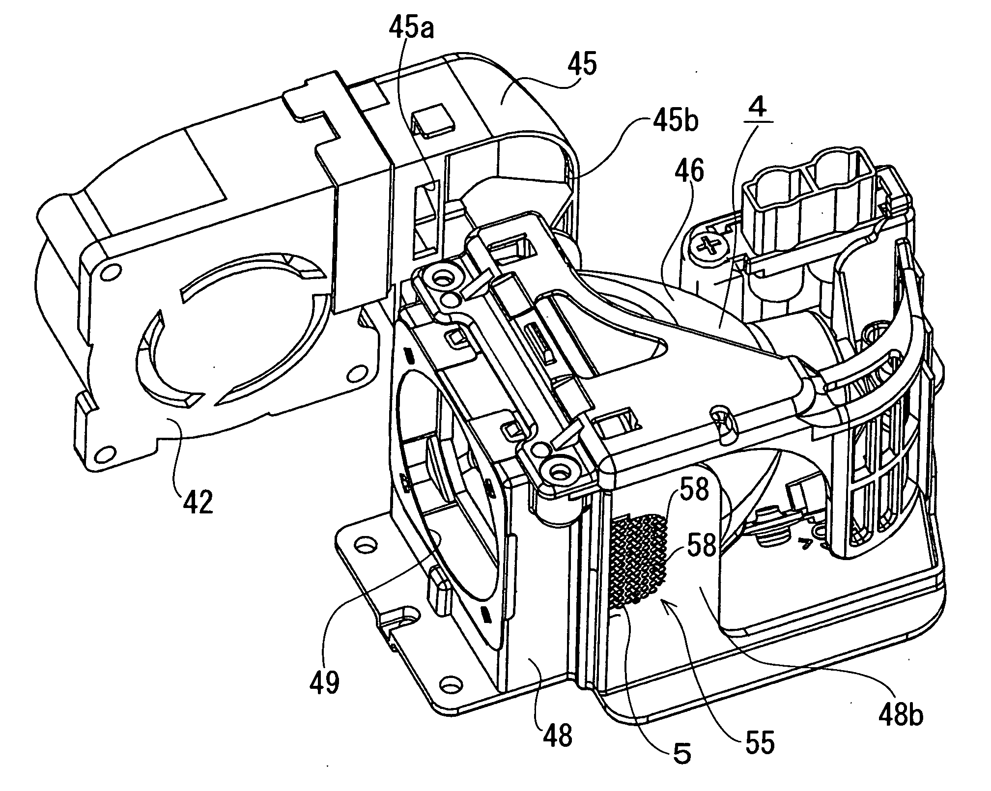
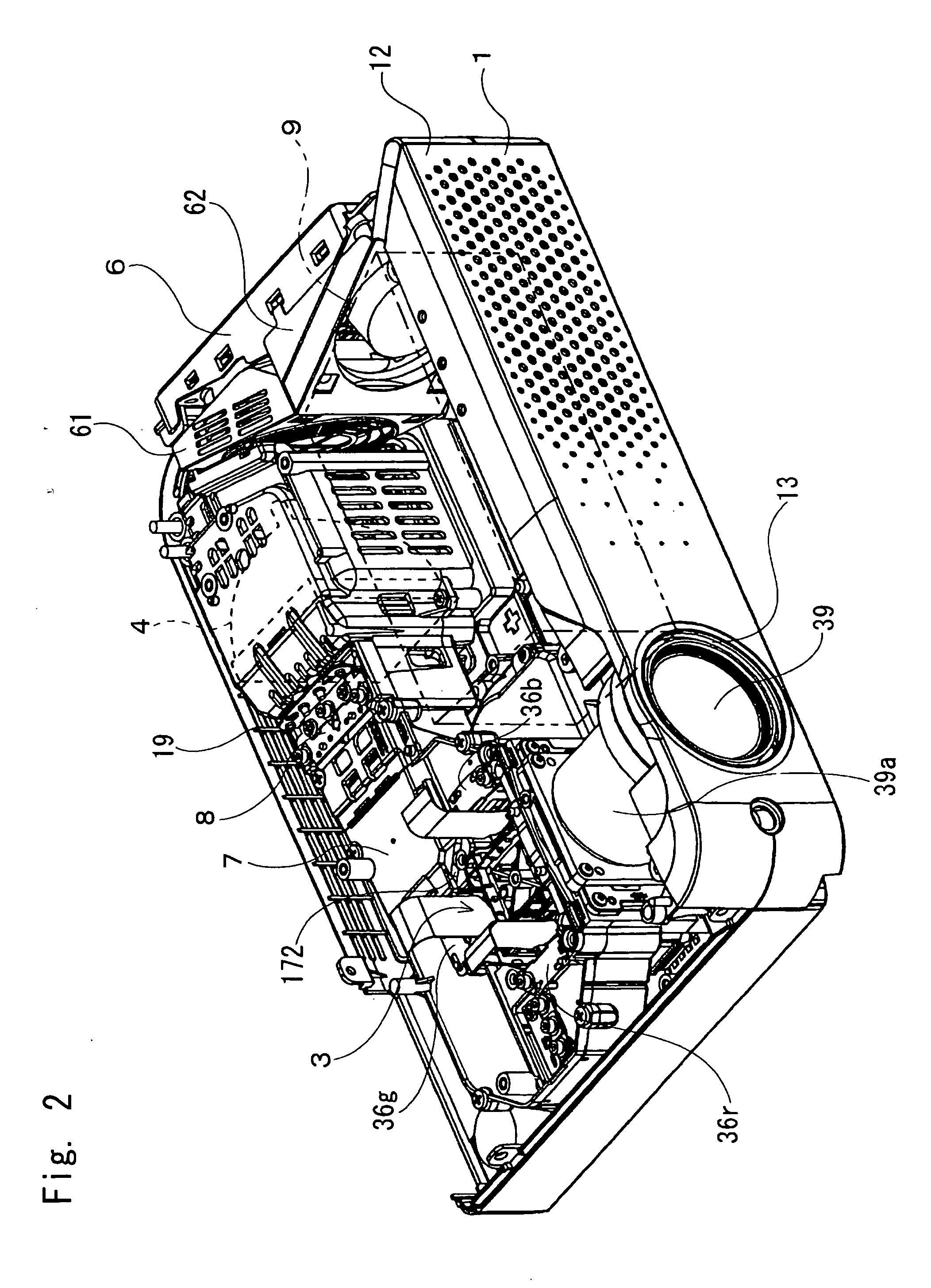
[0038] As shown in FIG. 2 and FIG. 3, a synthetic resin optical system holding case 7 extending in an ...


PUM


Abstract

A liquid crystal projector device of the present invention includes a lamp unit having a lamp and a reflector, and a cooling fan for cooling the lamp unit. The reflector includes a reflecting portion having a parabolic reflecting surface, and a plurality of side walls extending from the reflecting portion to surround the lamp. A first side wall of the plurality of side walls is provided with a first air intake opening and a second air intake opening for introducing air delivered from the cooling unit toward the lamp, at both sides of a plane including a central axis of the lamp and orthogonal to the first side wall. A wind blocking wall is defined between both air intake openings. An air discharge opening is formed on a second side wall opposed to the first side wall.

Description

[0001] The priority application Number 2005-220629 upon which this patent application is based is hereby incorporated by reference. BACKGROUND OF THE INVENTION [0002] 1. Field of the Invention [0003] The present invention relates to a projector device adapted to guide light from a light source to an optical system to generate image light for magnification projection on a forward screen. [0004] 2. Description of Related Art [0005] A conventional projector device of this type includes a casing having disposed therein a light source and an optical system including a polarization beam splitter, a polarizing plate, liquid crystal panels, a projection lens, etc. A discharge emission lamp unit such as a halogen lamp and a metal halide lamp is used as the light source. [0006] The lamp unit includes a lamp and a reflector for reflecting light emitted from the lamp toward the optical system. The lamp is formed by enclosing a luminous body inside a quartz bulb. The lamp is cooled by a cooling ...

Claims


Application Information

Patent Timeline
IPC IPC(8): G03B21/18
CPCG03B21/16
Inventor NAKAGAWA, NORIOSARUWATARI, TOSHIHIROTANAKA, KATSUMI
Owner SANYO ELECTRIC CO LTD
Why Eureka
Try Eureka