Arrangement in a liquid cooler

Active Publication Date: 2011-06-23
VACON OY
View PDF12 Cites 4 Cited by
  • Summary
  • Abstract
  • Description
  • Claims
  • Application Information

AI Technical Summary

Benefits of technology

[0013]What is essential for implementing the flow volume of the first route according to the invention is the combined surface area of the first apertures, which must be smaller than the inner cross-sectional area of the additional part, e.g. in the range of 30-70% of it. What is also essential is that the cross-sectional area remaining between the outer surface of the additional part and the inner surface of the main duct is sufficient, preferably at least as great as the inner cross-sectional area of the additional part, to enable a flow that is as free as possible from the transverse ducts into the apertures located near the ends of the additional part.
[0014]According to one preferred embodiment of the invention, the combined surface area of the apertures belonging to the first route is approx. one-half of the inner surface area of the additional part, in which case the liquid flow coming via the transverse ducts divides at normal flow rates such that approx. one-half of the liquid flows into the additional part via the first apertures and the remainder via the second apertures. This has an advantageous effect on the even division between the transverse ducts of the liquid flows because without the additional part the flow route is shorter than it and therefore the more unobstructed the closer to the external connections the transverse duct is located. A flow between the transverse ducts that is as uniform as possible is an advantage f

Problems solved by technology

The power of air cooling is, however, limited, for which reason liquid cooling is often used when the power density increases sufficiently.
In practical conditions the amount of liquid can sometimes, however, remain too small, in which case it is possible that the liquid circulates only via the lowermost transverse ducts, i.e.

Method used


Image

  • Arrangement in a liquid cooler
  • Arrangement in a liquid cooler
  • Arrangement in a liquid cooler

Examples


Example

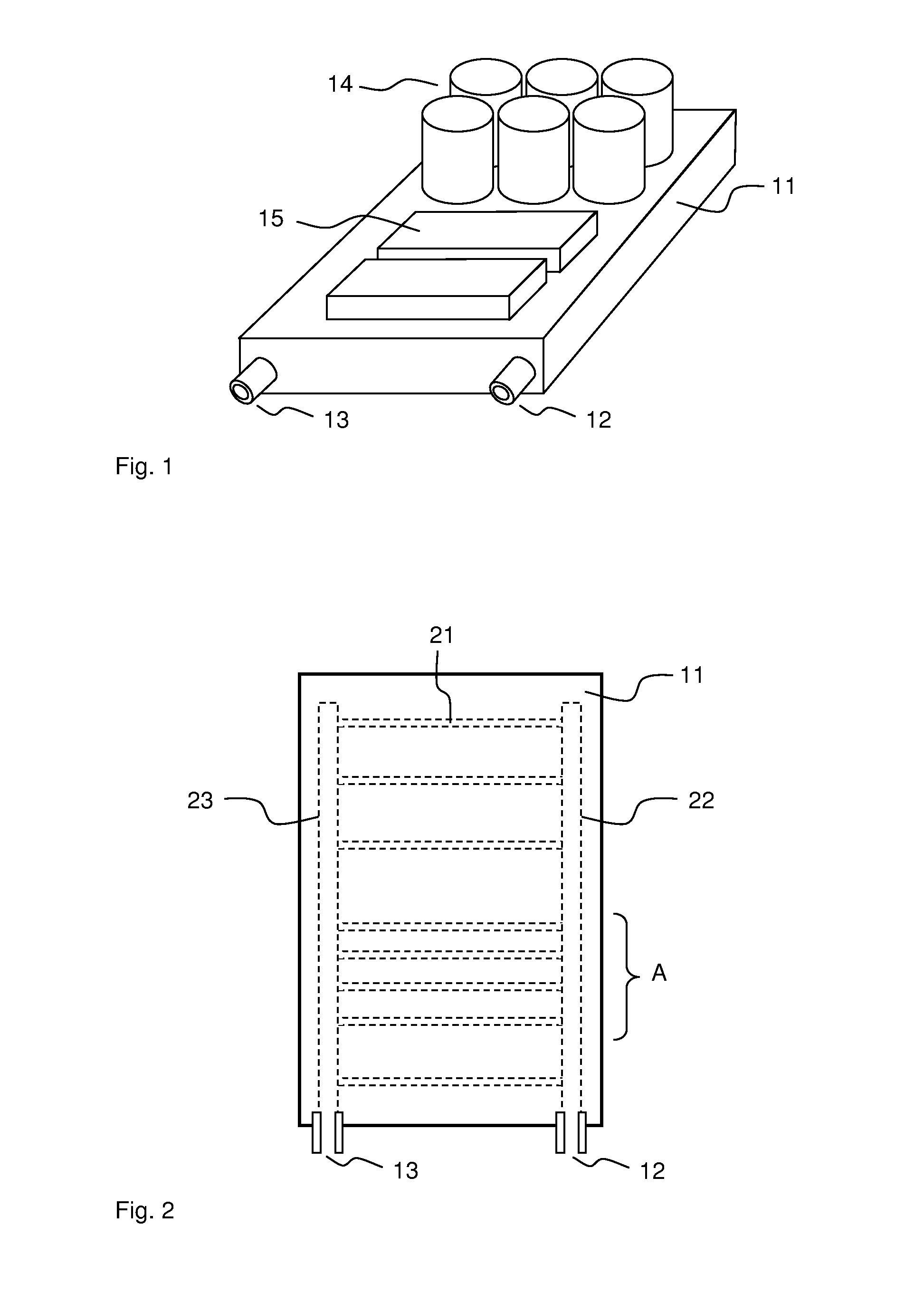
[0025]FIG. 1 presents the typical placement according to the invention of power components on a liquid cooler. For the sake of clarity, the figure is simplified and only the cooler and the essential parts from the viewpoint of the current invention are presented in it, but not e.g. the connection parts or fixing parts of components. In the figure, the external liquid circulation is connected to the cooler 11 via the input connector 12 and the output connector 13. The power components that require cooling, such as capacitors 14 and power semiconductor modules 15, are fixed, to achieve the most effective possible heat transfer, tightly against the cooler, e.g. by screwing or by compressing by means of suitable additional parts.

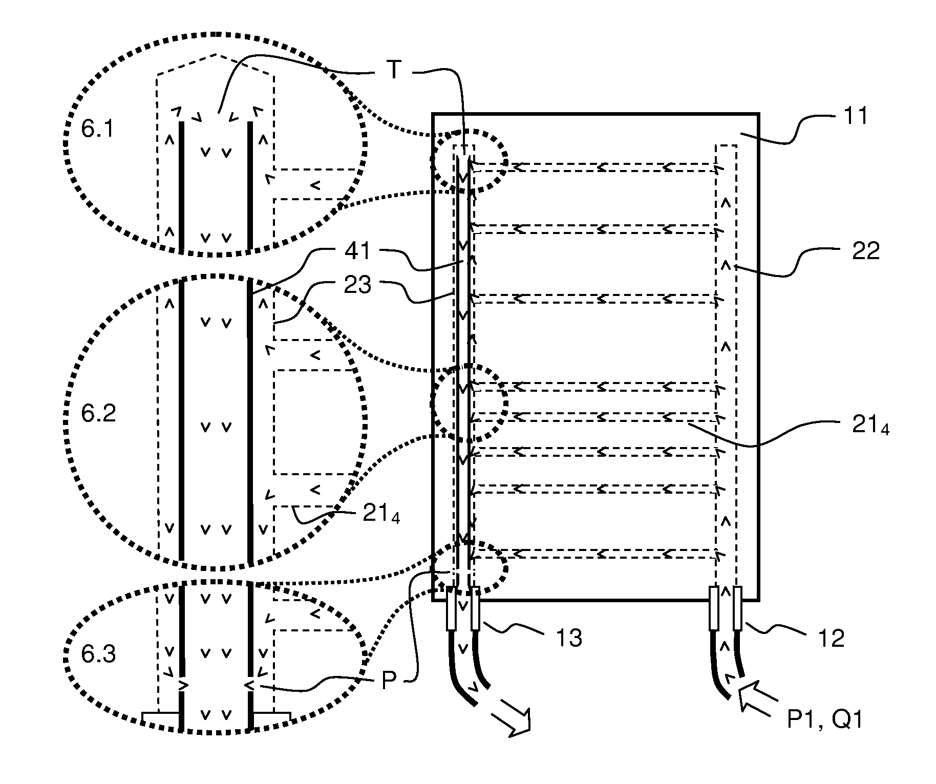
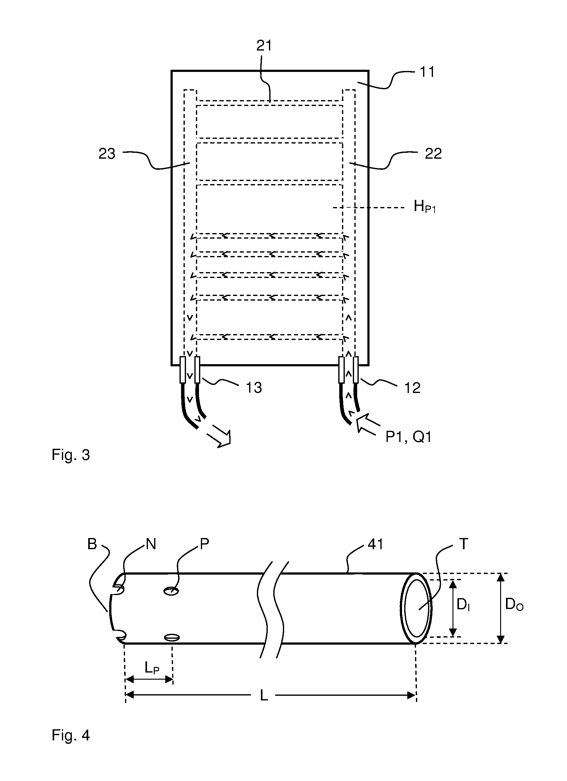
[0026]FIG. 2 presents one arrangement principle of the internal liquid ducting of a prior-art cooler, to such of which this invention can be applied and such of which has become known e.g. from patent publications U.S. Pat. No. 6,032,726 and U.S. Pat. No. 7,320,...


PUM


Abstract

Arrangement for circulating liquid in a liquid cooler (11) intended particularly for power electronics appliances, inside which cooler at least two longitudinal main ducts (22, 23) are arranged and transverse ducts (21) arranged between them and connecting them, and in which cooler at least one of the longitudinal ducts is an input duct (22), into which liquid from coming from outside is led via an input joint (12) and one is an output duct (23), from where the liquid is led out via the output joint (13), inside which output duct a tubular additional part (41) having an open end at least on the side of the output joint is installed, and which additional part is arranged detached from the output duct such that a gap remains between the outer surface of the additional part and the inner surface of the output duct for enabling a liquid flow in the output duct outside the additional part, and in which arrangement a first aperture or first apertures (P, N, P2) are arranged in the part of the additional part on the output joint side and/or in the output joint and/or between them for enabling a first path of passage for a part of the nominal total flow to the output joint, and a second aperture or second apertures (T, P1) are arranged in the part of the additional part that is farther from the output joint or between the additional part and the output duct for enabling a second path of passage for the remaining part of the total flow into the additional part and via it onwards to the output joint.

Description

FIELD OF TECHNOLOGY[0001]The object of this invention is a cooler that uses a liquid as a medium of heat transfer.PRIOR ART[0002]The general development trend of power electronics appliances, such as frequency converters, is a continuous increase in power density, i.e. the performance to be obtained from the appliance per unit of volume. The processing of power inside the appliances causes dissipation power and heating, which are generally proportional to the output power. To prevent overheating of the power components, the appliances require cooling, which must be more effective the higher the power density of the appliance is.[0003]The most common cooling method for power electronics appliances is air cooling, wherein cool air is blown, e.g. by means of a fan, into a cooler onto which the power component is fixed. The power of air cooling is, however, limited, for which reason liquid cooling is often used when the power density increases sufficiently. This is because the specific ...

Claims


Application Information

Patent Timeline
IPC IPC(8): F28F9/02
CPCH05K7/20927H01L23/473
Inventor KAMULA, PETRI
Owner VACON OY
Why Eureka
Try Eureka