Arrangement for a turbomachine

Active Publication Date: 2015-01-01
SIEMENS ENERGY GLOBAL GMBH & CO KG
View PDF3 Cites 3 Cited by
  • Summary
  • Abstract
  • Description
  • Claims
  • Application Information

AI Technical Summary

Benefits of technology

[0011]It is therefore an object of the present invention to protect the stato

Problems solved by technology

The high temperatures during operation of the turbomachine may damage the vane component, hence cooling of the vane component is important.
The vanes as well as the stator rings are subjected to hot gas flow which may cause damage to the

Method used


Image

  • Arrangement for a turbomachine
  • Arrangement for a turbomachine
  • Arrangement for a turbomachine

Examples


Embodiment Construction

[0026]Embodiments of the present invention relate to an arrangement for a turbomachine. The turbomachine may include a gas turbine, a steam turbine, a turbofan and the like.

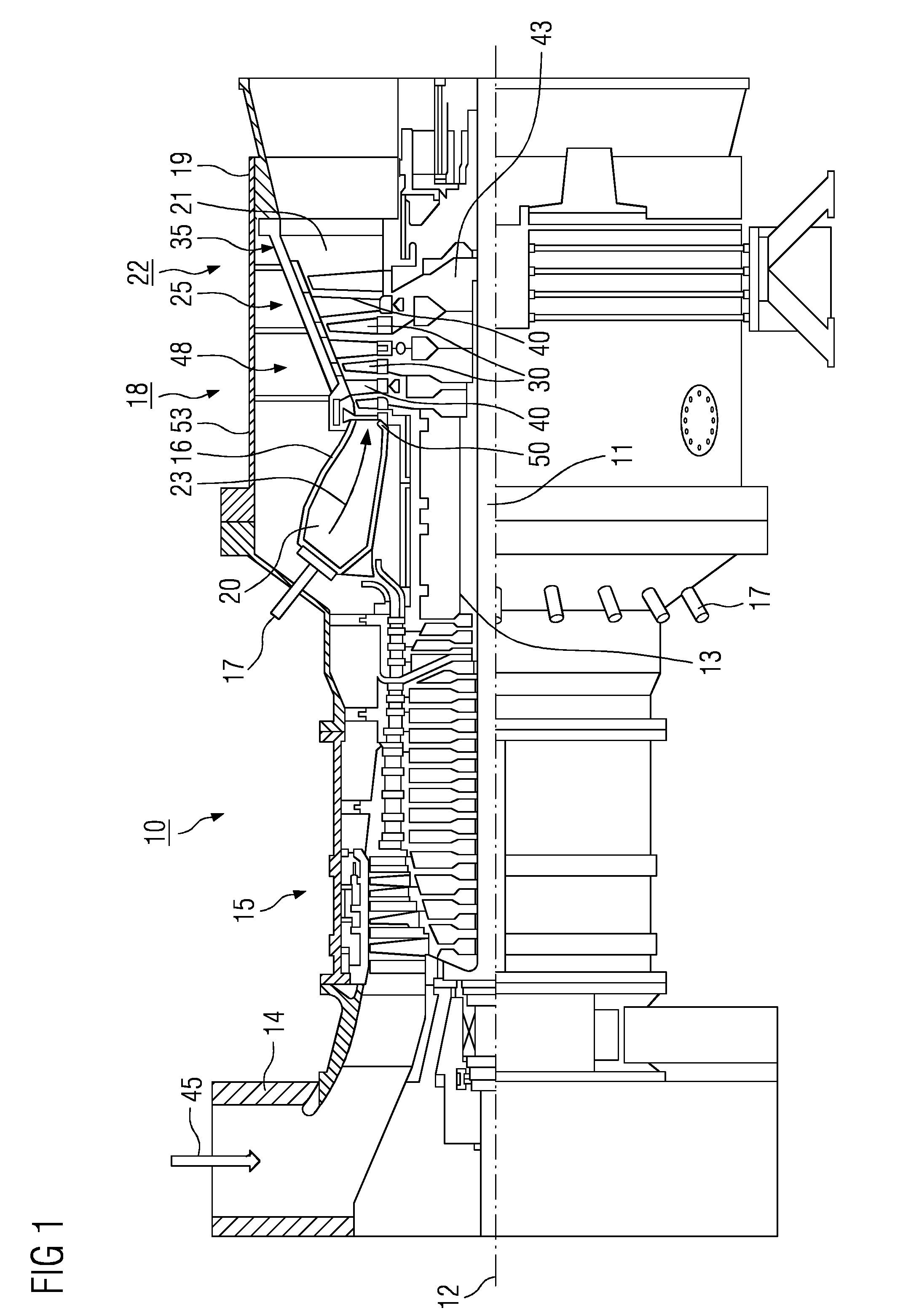
[0027]FIG. 1 is a schematic diagram of a turbomachine, such as a gas turbine 10 depicting internal components. The gas turbine 10 includes a rotor 13 which is mounted such that it can rotate along an axis of rotation 12, has a shaft 11 and is also referred to as a turbine rotor.

[0028]The gas turbine 10 includes an intake housing 14, a compressor 15, an annular combustion chamber 20 with a plurality of coaxially arranged burners 17; a turbine 18 and exhaust-gas housing 19 follow one another along the rotor 13.

[0029]The annular combustion chamber 20 is in communication with an annular hot-gas passage 21, where, by way of example, four successive turbine stages 22 form the turbine 18.

[0030]It may be noted that each turbine stage 22 is formed, for example, from two blade or vane rings. As seen in the direction of flo...


PUM

PropertyMeasurementUnit
Shapeaaaaaaaaaa

Abstract

An arrangement for a turbomachine is provided. The arrangement includes a vane for directing a hot gas during the operation of the turbomachine, a stator ring for securing the vane, a heat shield for protecting the stator ring from the hot gas flow wherein the heat shield is arranged in downstream direction of the hot gas flow in front of the stator ring characterized in that the heat shield comprises a plurality of channels formed therein for directing a cooling air.

Description

CROSS REFERENCE TO RELATED APPLICATIONS[0001]This application is the US National Stage of International Application No. PCT / EP2013 / 053898 filed Feb. 27, 2013, and claims the benefit thereof. The International Application claims the benefit of European Application No. EP12157286 filed Feb. 28, 2012. All of the applications are incorporated by reference herein in their entirety.FIELD OF INVENTION[0002]The present invention relates to an arrangement for a turbomachine.BACKGROUND OF INVENTION[0003]In modern day turbomachines various components of the turbomachine operate at very high temperatures. These components include the blade or vane component, which are in shape of an airfoil. In the present application, only “vane”, but the specifications can be transferred to a blade. The high temperatures during operation of the turbomachine may damage the vane component, hence cooling of the vane component is important. Cooling of these components is generally achieved by passing a cooling fl...

Claims


Application Information

Patent Timeline
IPC IPC(8): F01D25/12F01D9/04B23K26/38F01D25/14
CPCF01D25/12F01D9/04F01D25/14B23K26/388F05D2300/175F05D2230/40F05D2300/17F05D2300/177F05D2260/202F02C7/24Y10T29/49323F05D2240/15F01D9/041B23K26/389
Inventor GRANBERG, PERSZIJARTO, JANOS
Owner SIEMENS ENERGY GLOBAL GMBH & CO KG
Why Eureka
Try Eureka