X-ray tube

Active Publication Date: 2014-06-12
ELECTRONICS & TELECOMM RES INST
View PDF7 Cites 5 Cited by
  • Summary
  • Abstract
  • Description
  • Claims
  • Application Information

AI Technical Summary

Benefits of technology

The patent is for an X-ray tube that uses a field emitter to control the strength and timing of X-rays emitted. The tube also effectively releases heat generated by the anode. The rotation of the anode in the cooling oil results in better cooling efficiency. The technical effects of the invention include better control over X-ray properties, improved cooling of the anode, and improved performance of the X-ray tube.

Problems solved by technology

However, X-rays cannot be switched at a desired time due to a limitation in the thermal electron source.

Method used


Image

  • X-ray tube
  • X-ray tube
  • X-ray tube

Examples


Embodiment Construction

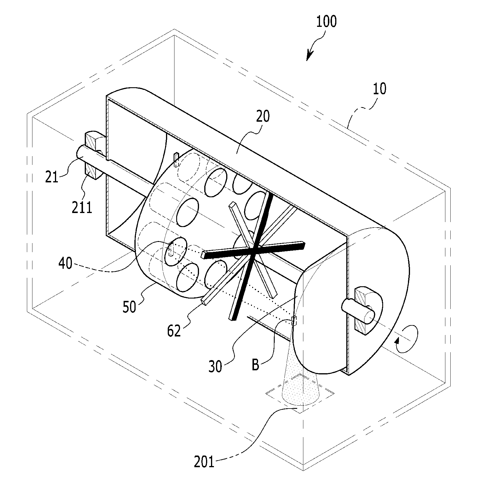
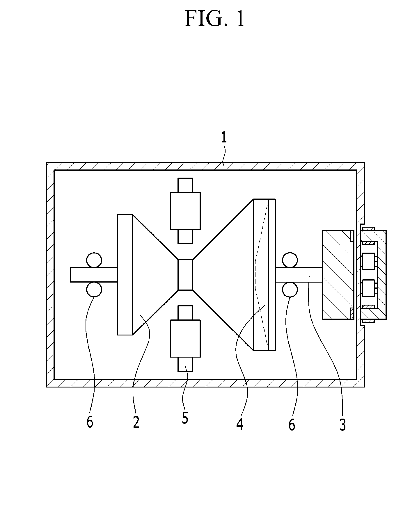
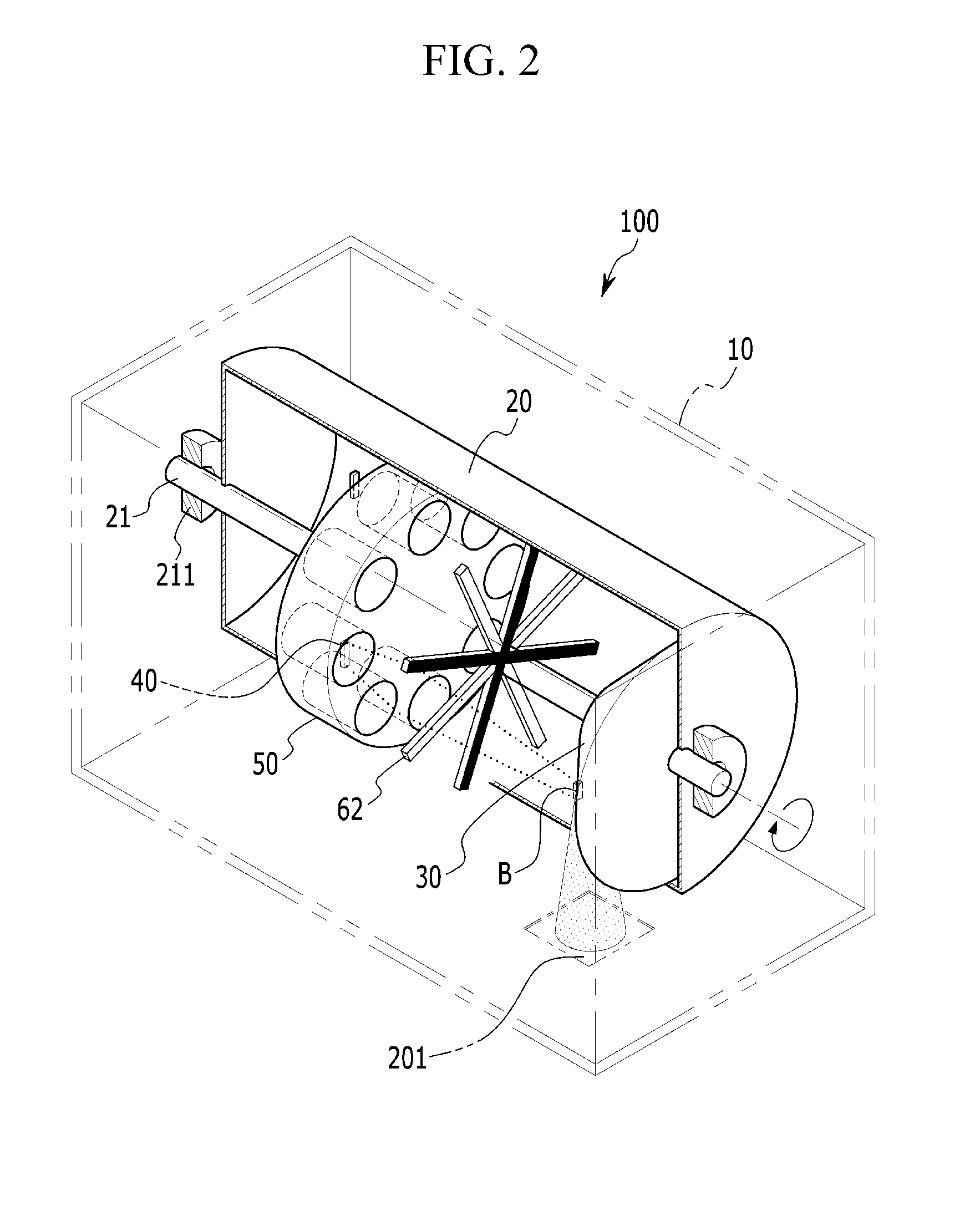
[0034]Hereinafter, the present invention will be described more fully with reference to the accompanying drawings, in which exemplary embodiments of the invention are shown. As those skilled in the art would realize, the described embodiments may be modified in various different ways, all without departing from the spirit or scope of the present invention. The drawings and description are to be regarded as illustrative in nature and not restrictive. Like reference numerals designate like elements throughout the specification.

[0035]Also, in various embodiments, the same reference numerals are used for components having the same configurations, and a first embodiment will be representatively described and only different configurations of other embodiments will be described.

[0036]To clarify the present invention, descriptions of irrelevant portions are limited, and like numbers refer to like elements throughout the specification.

[0037]Throughout this specification and the claims that f...


PUM


Abstract

An X-ray tube is provided. The X-ray tube includes a first housing including an X-ray window formed therein, a second housing being rotatable about a rotational shaft installed within the first housing, an anode installed on the rotational shaft within the second housing and positioned in one side of the rotational shaft in an extending direction of the rotational shaft, an emitter installed on the rotational shaft within the second housing, positioned in the other side of the rotational shaft in the extending direction of the rotational shaft, and emitting electron beams, a lens unit installed between the anode and the emitter and focusing the electron beams emitted from the emitter to the anode, and an electron beam deflection unit installed on the rotational shaft to deflect an angle of electron beams moving toward the anode from the lens unit.

Description

CROSS-REFERENCE TO RELATED APPLICATION[0001]This application claims priority to and the benefit of Korean Patent Application Nos. 10-2012-0142279 and 2013-0124816 filed in the Korean Intellectual Property Office on Dec. 7, 2012 and Oct. 18, 2013, the entire contents of which are incorporated herein by reference.BACKGROUND OF THE INVENTION[0002](a) Field of the Invention[0003]The present invention relates to an X-ray tube.[0004](b) Description of the Related Art[0005]An X-ray tube uses principle the fact that when a high voltage is applied between a cathode and an anode, a thermal electron source generated in the cathode configured as a filament collides with the anode as a metal to collide with electrons of the metal, producing X rays.[0006]The interior of the X-ray tube is maintained in a vacuum state to prevent molecular ionization in a movement path of high energy electron beams, thus preventing damage to the electron source due to dielectric breakdown or ion collision. A thickne...

Claims


Application Information

Patent Timeline
IPC IPC(8): H01J35/06H01J35/10
CPCH01J35/105H01J35/065H01J35/14H01J35/305H01J2201/30469H01J2235/068
Inventor JEONG, JIN WOOSONG, YOON-HOCHOI, SUNGYOULKANG, JUN TAEKIM, JAE-WOO
Owner ELECTRONICS & TELECOMM RES INST
Why Eureka
Try Eureka