Implementing enhanced bias configuration for CMOS inverter based optical transimpedence amplifier

a technology of optical transimpedance amplifier and inverter, which is applied in the field of data processing, can solve the problems of difficult control of these parameters, and achieve the effect of enhancing the bias configuration

Active Publication Date: 2016-08-04
IBM CORP
View PDF0 Cites 2 Cited by
  • Summary
  • Abstract
  • Description
  • Claims
  • Application Information

AI Technical Summary

Benefits of technology

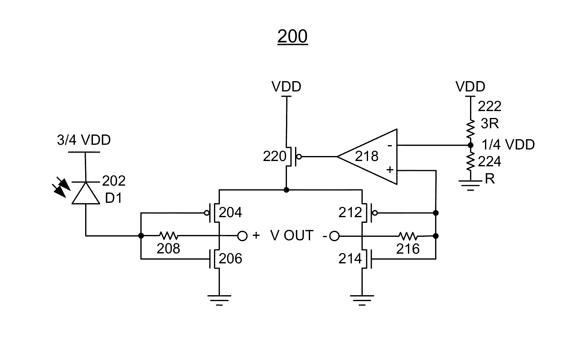
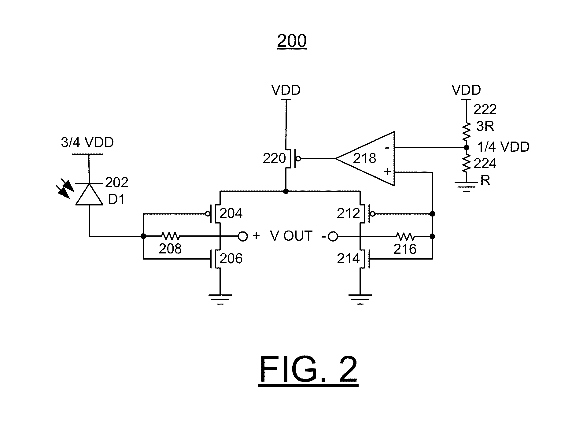
[0006]Principal aspects of the present invention are to provide a method and circuit for implementing an enhanced bias configuration for CMOS inverter based optical Transimpedance Amplifiers (TIAs), and a design structure on which the subject circuit resides. Other important aspects of the present invention are to provide such method, circuit and design structure substantially without negative effects and that overcome many of the disadvantages of prior art arrangements.
[0007]In brief, a method and circuit are provided for implementing an enhanced bias configuration for CMOS inverter based optical Transimpedance Amplifiers (TIAs). An operational amplifier is provided in a feedback configuration that forces an input of the TIA CMOS inverter to a set voltage level by regulation of the inverter power supply. A photo-detector sees a more stable bias voltage, and the responsivity of the photo-detector is more robust and the TIA has improved performance across process corners.

Problems solved by technology

Control of these parameters is difficult to achieve when the TIA input bias is not regulated.

Method used


Image

  • Implementing enhanced bias configuration for CMOS inverter based optical transimpedence amplifier
  • Implementing enhanced bias configuration for CMOS inverter based optical transimpedence amplifier
  • Implementing enhanced bias configuration for CMOS inverter based optical transimpedence amplifier

Examples


Embodiment Construction

[0018]In the following detailed description of embodiments of the invention, reference is made to the accompanying drawings, which illustrate example embodiments by which the invention may be practiced. It is to be understood that other embodiments may be utilized and structural changes may be made without departing from the scope of the invention.

[0019]The terminology used herein is for the purpose of describing particular embodiments only and is not intended to be limiting of the invention. As used herein, the singular forms “a”, “an” and “the” are intended to include the plural forms as well, unless the context clearly indicates otherwise. It will be further understood that the terms “comprises” and / or “comprising,” when used in this specification, specify the presence of stated features, integers, steps, operations, elements, and / or components, but do not preclude the presence or addition of one or more other features, integers, steps, operations, elements, components, and / or gr...


PUM


Abstract

A method and circuit are provided for implementing an enhanced bias configuration for CMOS inverter based optical Transimpedance Amplifiers (TIAs). An operational amplifier is provided in a feedback configuration that forces an input of the CMOS inverter to a set voltage level by regulation of the inverter power supply. A photo-detector sees a more stable bias voltage, and the responsivity of the photo-detector is more robust and the TIA has improved performance across process corners.

Description

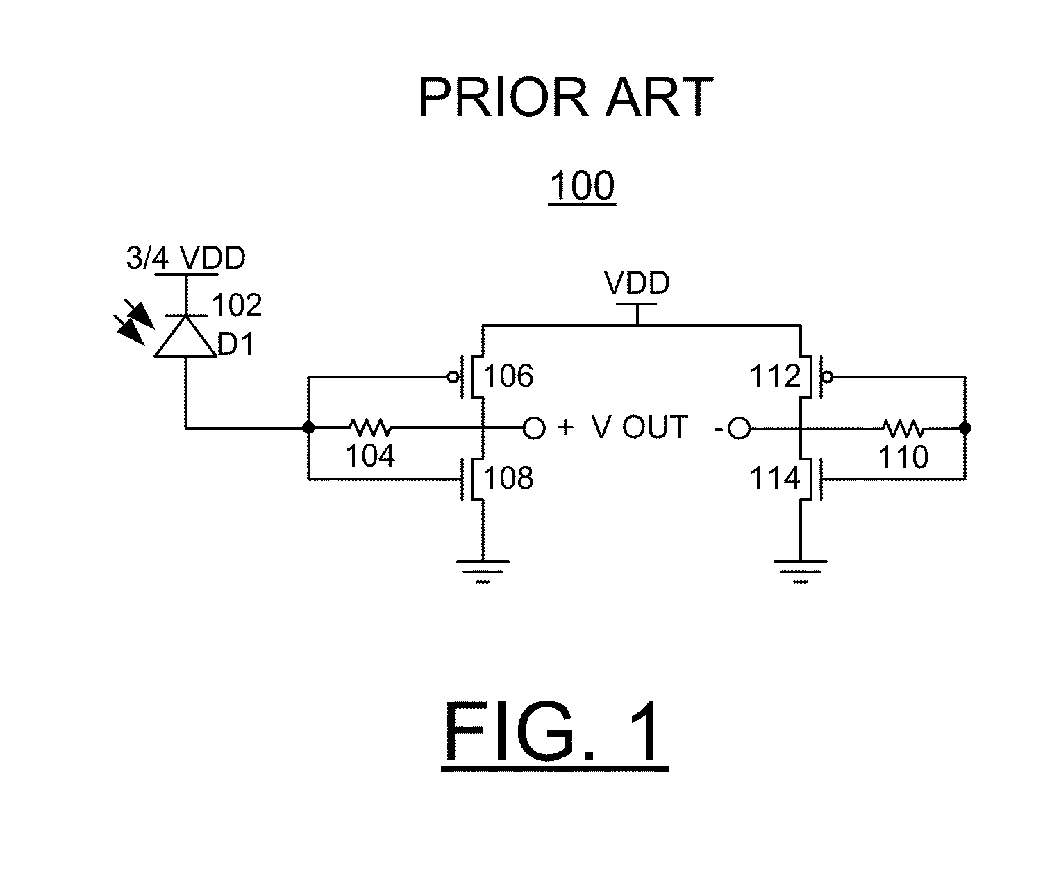
FIELD OF THE INVENTION[0001]The present invention relates generally to the data processing field, and more particularly, relates to a method and circuit for implementing an enhanced bias configuration for CMOS inverter based optical Transimpedance Amplifiers (TIAs), and a design structure on which the subject circuit resides.DESCRIPTION OF THE RELATED ART[0002]FIG. 1 illustrates complementary metal oxide semiconductor (CMOS) inverters with resistors in feedback that are often used as Transimpedance Amplifiers (TIAs) for the initial current to voltage conversion and amplification of a photo-detector output current. Although a TIA built as an inverter with a feedback resistor connected to a photo-detector will bias the photo-detector at ½ of VDD, this configuration has several drawbacks.[0003]First, the bias voltage of the input depends on matching the relative drive strength of the NFET and PFET devices. If due to process variations the PFET strength is higher than that of the NFET t...

Claims


Application Information

Patent Timeline
Patent Type & Authority Applications(United States)
IPC IPC(8): H03F3/08
CPCH03F3/08H03F2200/153H03F3/45179H03F3/082H03F3/45183H03F2203/45264
Inventor FRANK, MATTHEW B.PROESEL, JONATHAN E.RICHETTA, RAYMOND A.
Owner IBM CORP
Why Eureka
Try Eureka