Communication system

a communication system and communication technology, applied in the field of communication systems, can solve the problems of introducing delays, and the x2-gw may be particularly heavy

Active Publication Date: 2016-08-04
NEC CORP
View PDF0 Cites 25 Cited by
  • Summary
  • Abstract
  • Description
  • Claims
  • Application Information

AI Technical Summary

Benefits of technology

[0054]Although for efficiency of understanding for those of skill in the art, the invention will be described in detail in the context of a 3G system (UMTS, LTE), the principles of the invention can be applied to other systems (such as WiMAX) in which (home / small cell) base stations communicate via a signalling gateway with the corresponding elements of the system changed as required.

Problems solved by technology

Such updates may thus result in frequent re-configuration of the X2 connections between neighbouring base stations necessitating exchange of appropriate X2 signalling between them.
Moreover, where there are a large number of items of user equipment (UEs) such as mobile (cellular) telephones, or the like, moving between cells, the amount of X2 signalling for facilitating the mobility of the UEs, handled by the X2-GW may also be particularly heavy.
Whilst this procedure ensures that the base stations can send X2AP messages securely via an X2-GW, a significant amount of processing is required, at the X2-GW, which introduces delays and / or limits the number of messages that can be concurrently processed by the X2-GW.
This is a particular issue given the potentially large number, and relatively high frequency, of X2AP messages that will likely be sent via the X2 gateway especially when there are a large number of base stations (LPNs and macro) connected via a single X2 gateway.

Method used


Image

  • Communication system
  • Communication system
  • Communication system

Examples


first embodiment

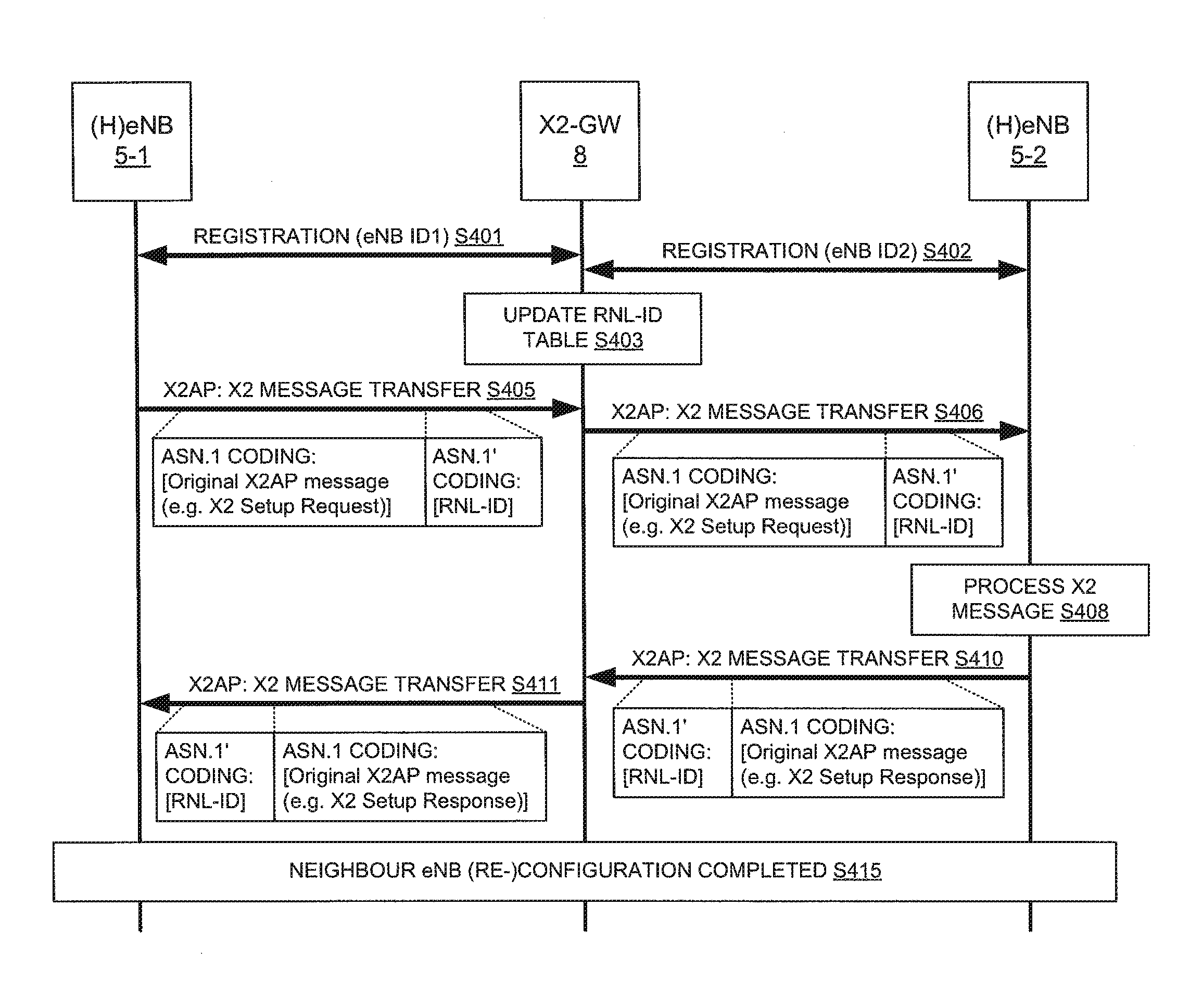
[0094]FIG. 4 is an exemplary timing diagram illustrating a method performed by components of the mobile telecommunication system 1 of FIG. 1 whilst carrying out an exemplary embodiment of the invention.

[0095]Initially, as shown respectively in steps S401 and S402, the base stations 5-1 and 5-2 each register with the X2-GW 8 so that the X2-GW 8 is aware of the current operating state of these base stations. For simplicity, the registration procedure is illustrated as a single step, although it will be appreciated that it may require the exchange of a plurality of messages (e.g. a registration request by the base station 5 and a corresponding approval / acknowledgement / failure by the X2-GW 8).

[0096]As can be seen, as part of the registration procedure, the first and the second base stations 5 inform the X2-GW 8 (e.g. by sending a suitable signalling message) about their respective RNL-IDs (denoted ‘eNB ID1’ and ‘eNB ID2’, respectively) using which X2 signalling can be routed to these ba...

second embodiment

[0105]FIG. 5 schematically illustrates an exemplary protocol stack for implementing an exemplary embodiment of the invention.

[0106]As can be seen, the base stations 5 each implements a standard protocol stack as specified by in the relevant 3GPP standards. The standard protocol stack, starting from the lowest layer, includes:[0107]a physical layer, which specifies physical and electrical characteristics of the network, and handles the transmission of information over a network medium (e.g. cable or radio link);[0108]a data link layer, which is responsible for addressing, i.e. labelling information for a particular destination location, and for encapsulation of higher-level messages into frames that are sent over the network at the physical layer;[0109]an Internet Protocol (IP) layer, which is responsible for communicating data formatted in accordance with the IP protocol, using the services provided by the data link layer;[0110]a Stream Control Transmission Protocol (SCTP) layer, wh...

third embodiment

[0128]FIG. 7 schematically illustrates another exemplary protocol stack for implementing an exemplary embodiment of the invention.

[0129]As can be seen, the base stations 5 and the X2-GW 8 each implements the standard protocol stack as described above with reference to FIG. 5 (i.e. a physical layer, a data link layer, an IP layer, an SCTP layer, and an X2AP layer (although the X2AP layer is optional in case of the gateway of this example).

[0130]As also shown in FIG. 7, there is a first SCTP association (denoted ‘SCTP1’) between the first base station 5-1 and the X2-GW 8 for communicating X2AP messages between them, and there is a second SCTP association (denoted ‘SCTP2’) between the X2-GW 8 and the second base station 5-2 for communicating X2AP messages between them. Accordingly, the first base station 5-1 can communicate X2 PDU(s) to the second base station 5-2 by sending a first X2AP message to the X2-GW 8 using the corresponding first SCTP association. The PDU(s) included in the f...


PUM


Abstract

A communication system is disclosed comprising a gateway and a number of base stations communicating, via the gateway, in accordance with a base station to base station application protocol. The gateway receives a message from a first base station, destined for a second base station. The message comprises (a) information for the second base station, in a first part of the message; and (b) an identifier of the second base station, in a second part of the message other than the first part. The gateway can obtain from the received message the second base station's identifier without the gateway being required to obtain the information from the first part of the message. The gateway routes the message to the second base station identified by the obtained identifier.

Description

TECHNICAL FIELD[0001]The present invention relates to a communication system and to components thereof for providing communication services to mobile or fixed communication devices. The invention has particular but not exclusive relevance to the implementation of a so-called X2 gateway (a gateway that connects ‘small’ cells or Low Power Nodes (LPNs) and regular base stations using an X2 protocol) in Long Term Evolution (LTE) communication systems currently being developed by the 3rd Generation Partnership Project (3GPP).BACKGROUND ART[0002]In 3GPP LTE networks, a base station (i.e. evolved NodeB, eNB) of a Radio Access Network (RAN) transmits data and signalling between a core network (CN) and User Equipment (UEs) located within the base station's coverage area.[0003]Recent developments in communication networks have seen increased deployment of so called ‘small’ cells operated by Low Power Nodes (LPNs), such as pico eNBs, femto eNBs, Home eNBs (HeNBs) or the like, which cells have ...

Claims


Application Information

Patent Timeline
Patent Type & Authority Applications(United States)
IPC IPC(8): H04W36/00
CPCH04W88/16H04W84/045H04W36/0077H04W36/0061H04W40/22
Inventor SIVAVAKEESAR, SIVAPATHALINGHAMGUPTA, NEERAJ
Owner NEC CORP
Why Eureka
Try Eureka