Medical imaging method varying collimation of emitted radiation beam

Active Publication Date: 2016-08-11
GENERAL ELECTRIC CO
View PDF6 Cites 9 Cited by
  • Summary
  • Abstract
  • Description
  • Claims
  • Application Information

AI Technical Summary

Benefits of technology

[0006]The object of the present invention is to alle

Problems solved by technology

But none of them use collimation variation of emitted

Method used


Image

  • Medical imaging method varying collimation of emitted radiation beam
  • Medical imaging method varying collimation of emitted radiation beam
  • Medical imaging method varying collimation of emitted radiation beam

Examples


Embodiment Construction

[0040]In all following part of the text, except if otherwise specified, when radiation is used, X-ray which is a specific radiation could be used instead as well. Both applications, on the one hand to radiation in general and on the other hand to X-ray in particular, are intended to be covered. In a similar way, when C-arm is mentioned, any other type of gantry, for example gantry of a computed tomography scanner, unless otherwise specified, could be used instead of the C-arm.

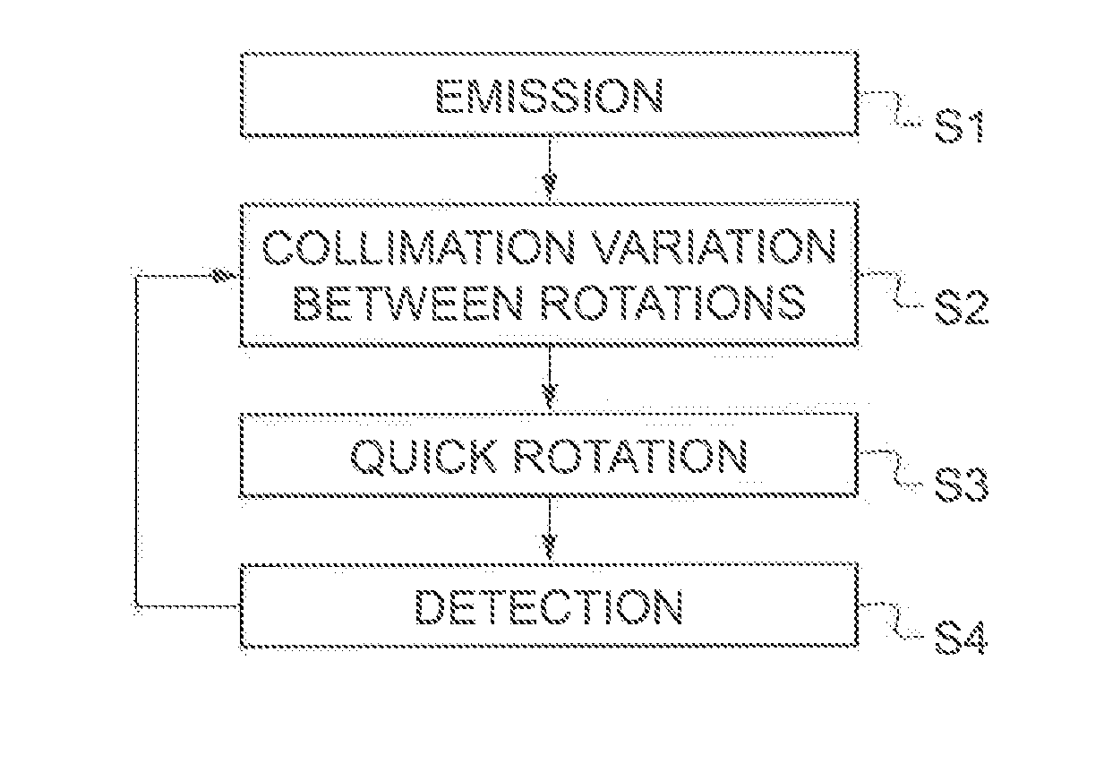
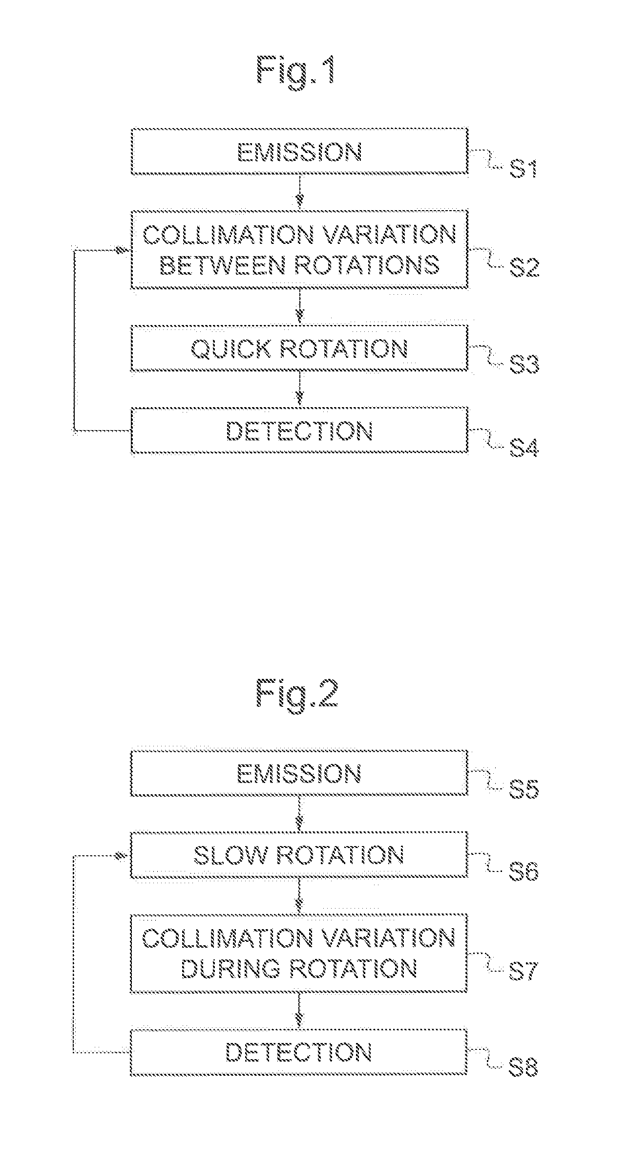
[0041]FIG. 1 shows an example of an embodiment of a medical imaging method varying the collimation of the emitted radiation beam according to the invention. The medical imaging method varying the collimation of the emitted radiation beam comprises a step S1 of emission, a step S2 of collimation variation between rotations, a step S3 of quick rotation, a step S4 of detection.

[0042]In the step S1 of emission, a radiation beam is emitted by a radiation source which is supported by a C-arm of a medical imaging syst...


PUM


Abstract

This invention relates to a medical imaging method comprising: emitting a radiation beam from a radiation source of a rotating gantry, preferably of a rotating C-arm, on a volume of interest, varying collimation of said emitted radiation beam so as to change at least part-time a field of view of said emitted radiation beam so that there are at least a first part and a second part of said volume of interest such that, when said first part of said volume of interest is imaged, said second part of said volume of interest is shuttered, and when said second part of said volume of interest is imaged, said first part of said volume of interest is shuttered.

Description

[0001]Single-use bioreactor systems are commonly used for cell culture applications. The growth and culture of mammalian cells, for instance, typically require a constant supply of adequate oxygen. Oxygen diffusion in culture media is a function of a liquid-to-air surface area when operating the bioreactor. Furthermore, oxygen transfer is limited by the liquid-to-air surface area and any shear forces created by agitation and / or sparging.FIELD OF THE INVENTION[0002]The invention relates to medical imaging methods and to associated medical imaging systems.BACKGROUND OF THE INVENTION[0003]According to a first prior art, for example described in U.S. Pat. No. 7,983,391B2, there is a movable radiation shield reducing radiation exposure. In a volume of interest, only a center part of higher interest is refreshed more often than a surrounding part of lower interest. The radiation detector is not rotating. There is radiation exposure lowering. However, there is no scattered radiation loweri...

Claims


Application Information

Patent Timeline
IPC IPC(8): A61B6/06A61B6/00
CPCA61B6/06A61B6/107A61B6/4441A61B6/4035A61B6/4021G21K1/02G21K1/04H01J35/025H01J37/023
Inventor RIDDELL, CYRILTROUSSET, YVES LUCIEN
Owner GENERAL ELECTRIC CO
Why Eureka
Try Eureka