Transparent Ballistic Resistant Composite

a composite and ballistic technology, applied in the field of ballistic shields, can solve the problems of business installations and homes, people and property being subject to similar ballistic attacks, offensive ordnance, explosive devices and accompanying shrapnel, etc., and achieve the effect of increasing the ballistic protection of windows and interior occupants or properties

Inactive Publication Date: 2016-08-11
MILSPRAY
View PDF3 Cites 1 Cited by
  • Summary
  • Abstract
  • Description
  • Claims
  • Application Information

AI Technical Summary

Benefits of technology

[0009]A ballistic resistant polymeric composition may be present as an internal core layer of a multilayer composite having a transparent, more rigid plastic substrate, such as poly(methyl methacrylate), or glass outer substrate layer that protects the core layer from environmental damage from scratches, dirt, pollution, and weather caused by exposure to abrasion, wind, rain, ice, and sun. The polymeric composition also can be present in multiple layers alternating between glass and polymer, or as a coating to a single side of a transparent substrate. The composite can be applied directly on an existing window glazing structure to increase ballistic protection of the window and interior occupants or property. The composite optionally also may include a second layer of more rigid plastic or glass facing the opposite surface of the composite, so that the window glazing comprises a hard surface on opposite sides of the ballistic energy absorbing polymeric barrier core layer. This dual skin composite can serve as a ballistic resistant window in a new building or vehicle installation. Alternatively, it can be a complete substitute for an existing non-ballistic resistant glazing structure that is removed and replaced by the dual skin composite.

Problems solved by technology

Aggressive threats to people and property exist in modern society from a wide variety of military and civilian activities.
In the military and police spheres, personnel and equipment carrying out operations are subject to attack by offensive ordnance, explosive devices and accompanying shrapnel.
Apart from the military, people, business installations and homes are exposed to similar ballistic attack resulting from criminal activity, social unrest, irrationally aggressive behavior and the like.
Additionally, many existing ballistic shields are visually opaque so that a person protected by a shield cannot view a threat on the other side of the shield.
Opaque shields are thus less desirable for applications such as window protection.
Destructive forces are increasingly affecting the integrity of elements of civil engineered and architectural infrastructure, such as building foundations, bridge support columns and the like.
Intentional and accidental destruction from such causes as malicious or military explosive detonations and accidental collisions can severely damage the strength of such infrastructure elements.
Wear and tear caused by age and normal use and environmental exposure can also damage infrastructure elements such as building foundations, utility towers and culverts, roadway structures and the like.
Weakened and deteriorating structures, especially those of cured solid construction material such as concrete and cement, is often manifested as spalling, in which surface cracks appear and propagate and the surface layers chip and flake off.
Although the coating may be less than ten mils in thickness, preferably less than five mils in thickness, more preferably less than one mil in thickness, deterioration such as spalling below the coating cannot be observed by visual inspection because of coating opacity.
Testing for structural defects thus requires application of expensive, sensitive, and technologically sophisticated analytical instrumentation with trained and skilled technicians to evaluate the results.

Method used


Image

  • Transparent Ballistic Resistant Composite
  • Transparent Ballistic Resistant Composite
  • Transparent Ballistic Resistant Composite

Examples


examples

[0054]Urethane polymer compositions were prepared using material compositions formulated as in Table III, below.

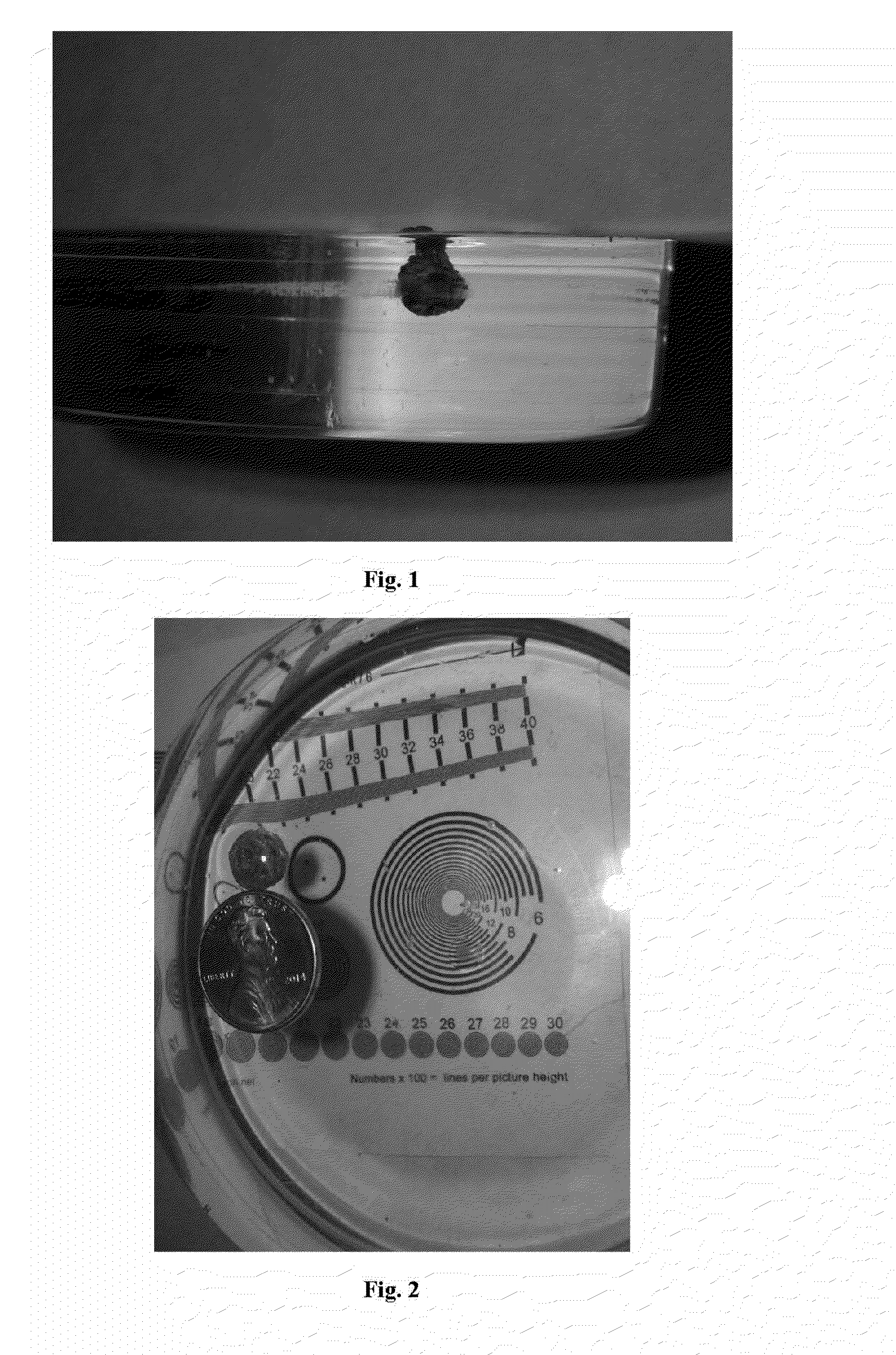
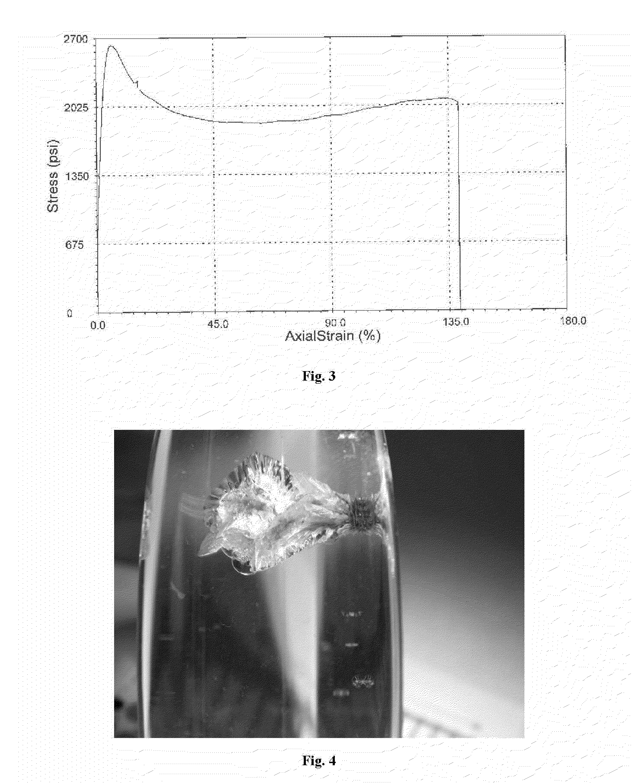
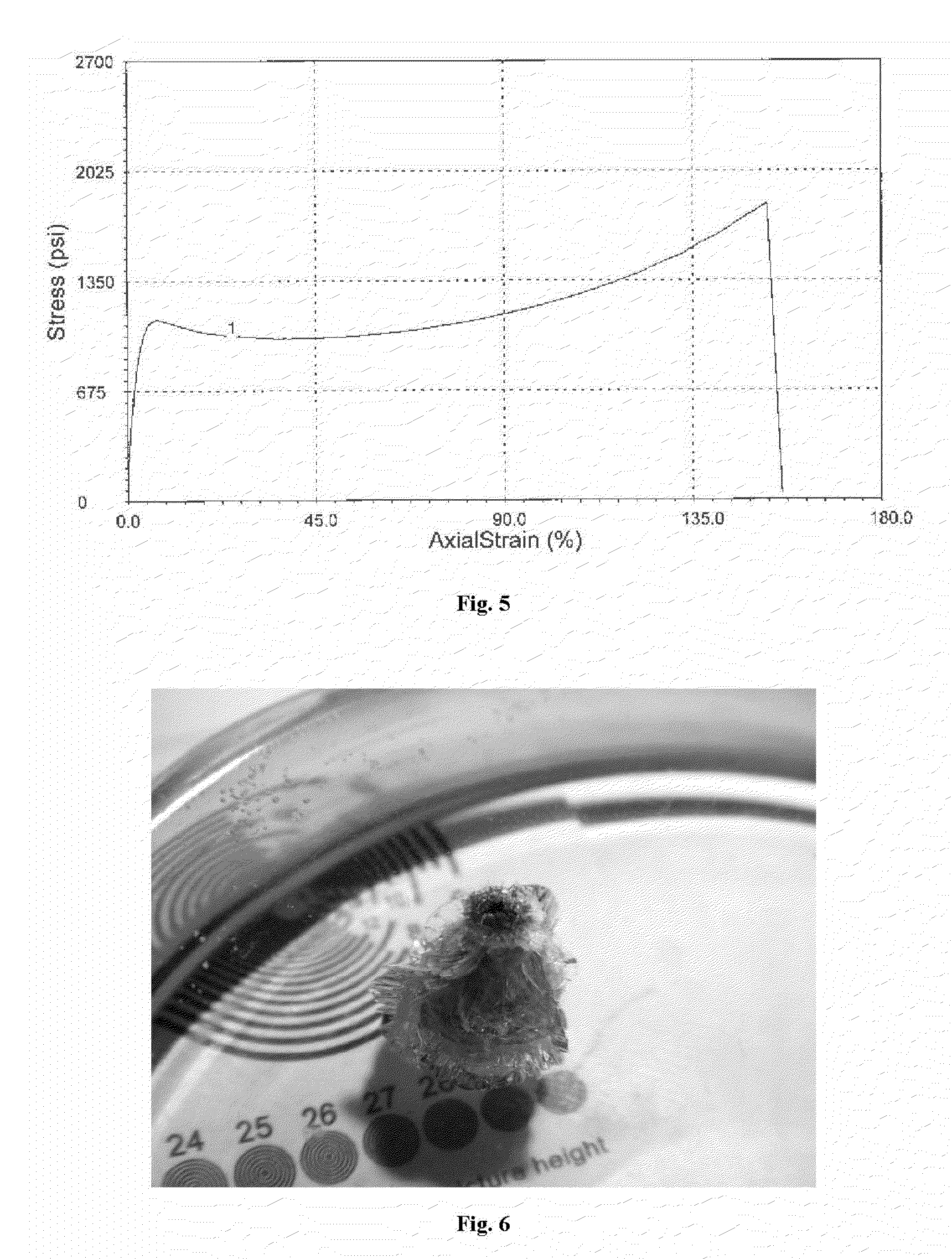
[0055]The isocyanate components were mixed to form an isocyanate blend and the polyol components were mixed to form a polyol blend. Methyl amyl ketone or acetone and the silane were placed in a container and mixed with a Cowles blade rotary shear agitator at 50 to 100 rev. / min until homogeneous. The isocyanate blend was added to the container and agitation continued at 650-700 rev / min until a homogeneous mixture was obtained. Then, the polyol blend was added to the container and agitation continued at 650-700 rev / min until a homogeneous mixture was obtained. All materials were maintained and mixed at about 38° F. The resulting mixture was degassed in a vacuum chamber at a pressure below 0.4 inches Hg. vacuum was maintained for approximately 8 min until all volatile components had been removed from the mixture. The uncured, liquid mixture was coated onto the surface of a gl...


PUM

PropertyMeasurementUnit
wt %aaaaaaaaaa
wt %aaaaaaaaaa
thicknessaaaaaaaaaa

Abstract

A composition comprising clear urethane polymer that has elastomeric properties provides resistance to damage by impact from ballistic projectiles. The composition can be monolithic urethane polymer or a composite with a urethane polymer core layer and a transparent protective substrate layer adjacent one or both planar surfaces of the polymer.

Description

RELATED APPLICATIONS[0001]This application claims benefit to U.S. provisional application 62 / 114,532, filed Feb. 10, 2015, which is incorporated herein by reference.FIELD OF THE INVENTION[0002]This invention relates to ballistic shields. More specifically, it relates to a transparent composite polymeric core layer for ballistic shields that can safely absorb impact from weapons-grade projectiles, shrapnel and other ballistic projectiles. The invention also may comprise a layer of material external to the core layer that protects the core layer.[0003]The invention also may relate to a clear polymeric coating that can be applied to infrastructure substrates, such as metal, stone or concrete construction components, such as building foundations or bridge supports, so as to protect the surface of those substrates and to provide visual inspection of the physical condition of the substrate material.BACKGROUND OF THE INVENTION[0004]Aggressive threats to people and property exist in modern ...

Claims


Application Information

Patent Timeline
Patent Type & Authority Applications(United States)
IPC IPC(8): C09D175/04F41H5/04F41H5/06
CPCC09D175/12F41H5/06F41H5/0407C09D175/04C08G18/6651C08G18/792C09D175/06C08G18/3821C08G18/44F41H5/24
Inventor JOHNSTON, MATTHEW L.CRUZ, KEVIN J.
Owner MILSPRAY
Why Eureka
Try Eureka