Cavity filter and RF communication device with the cavity filter

a cavity filter and communication device technology, applied in waveguide devices, basic electric elements, resonators, etc., can solve the problems of increasing the occupied space of the whole system, complex process, and relatively high material cost and processing cost, so as to simplify the installation procedure and reduce the length, the effect of reducing the installation procedure and the cos

Active Publication Date: 2016-08-11
ANHUI TATFOOK TECH CO LTD
View PDF2 Cites 17 Cited by
  • Summary
  • Abstract
  • Description
  • Claims
  • Application Information

AI Technical Summary

Benefits of technology

[0029]Compared with the prior art, the cavity filter provided by embodiments of the present disclosure utilizes the elastic deformation of the resonance rod, which may thus change its length, to adjust the RF parameters, therefore eliminating the need for the prior art resonance rod disposed within the cavity, compressing the space of the entire cavity, and reducing the installation procedures and the cost. Furthermore, the tuning screw is disposed within the resonance rod and connected by a supporting member without the need of using a nut and a washer on the cover plate, thus simplifying the installation procedures, reducing the length of portion of the tuning screw exposed outside the cover plate and thus compressing the space of the entire cavity. In addition, the tuning screw is disposed outside the resonance cavity, thus optimizing the interactivity and tunability of the product and enhancing the performance of the entire product.

Problems solved by technology

Through study and practice on the prior art, inventors of the present disclosure have found that, in the prior art, certain space would be needed above the cover plate for accommodating the nut, the washer and the exposed portion of the tuning screw, which may increase the occupied space of the whole system; and that, when fitting the tuning screw, it will be needed to mount the nut and the washer so that the process is complicated and the material cost and the processing cost are relatively high.

Method used


Image

  • Cavity filter and RF communication device with the cavity filter
  • Cavity filter and RF communication device with the cavity filter
  • Cavity filter and RF communication device with the cavity filter

Examples


Embodiment Construction

[0045]Below a definite and complete description will be made on the technical solutions according to embodiments of the present disclosure with reference to the accompanying drawings of embodiments of the present disclosure. Apparently, the described embodiments are merely some but not all of the embodiments of the present disclosure. Based on the embodiments of the present disclosure, all other embodiments obtained by one of ordinary skill in the art without making inventive efforts shall all fall within the protection scope of the present disclosure.

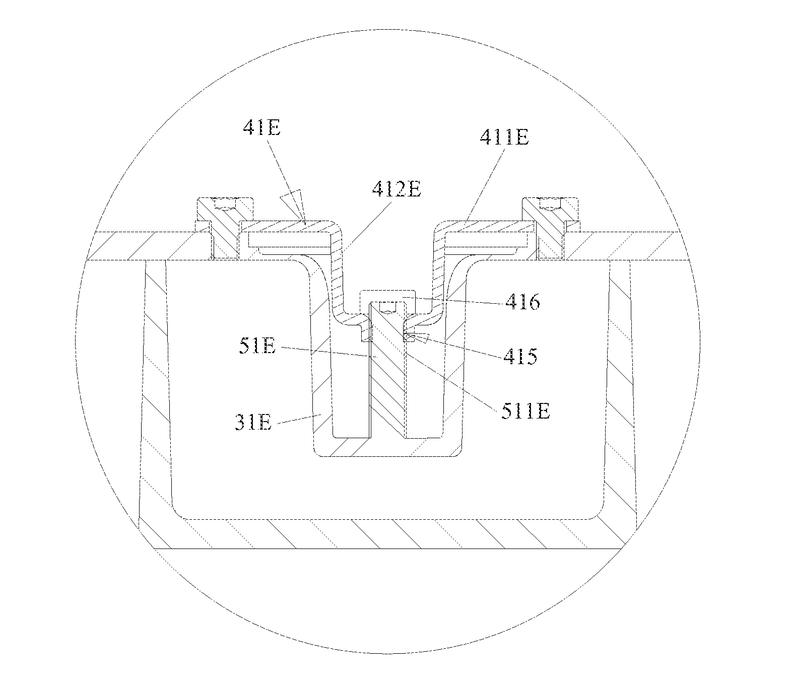
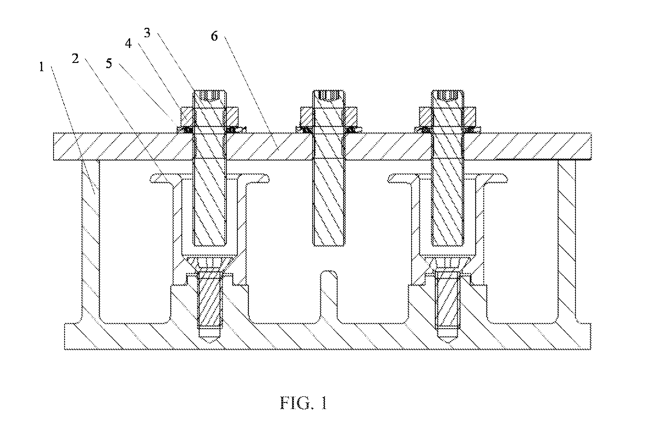
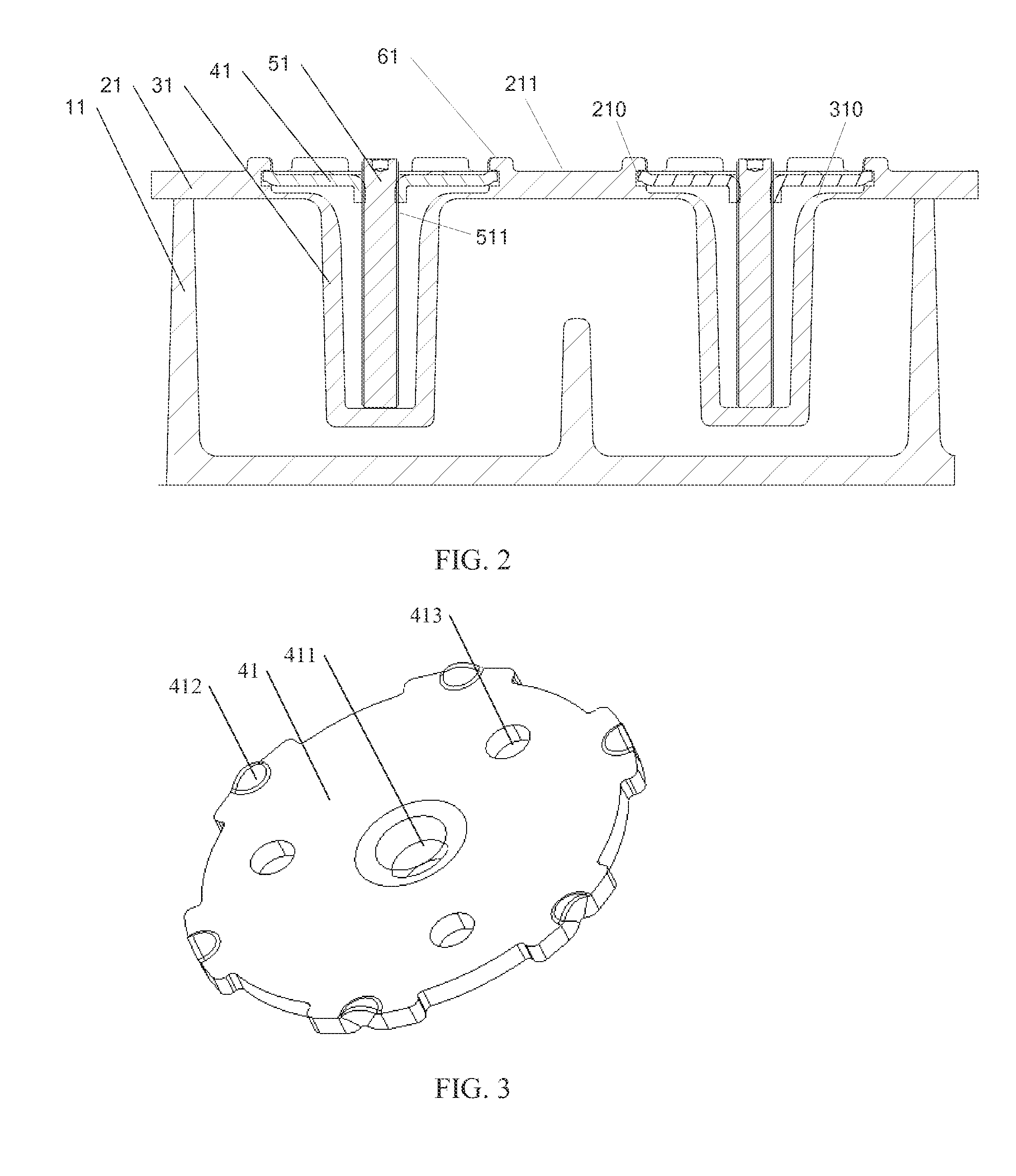
[0046]A cavity filter is provided, comprising a cavity body, a cover plate, a resonance rod and a tuning screw. The cover plate caps the cavity body to form a resonance cavity. The resonance rod is a tubular body opening at one end, and is formed integrally with the cover plate or the cavity body. The opening end of the resonance rod is combined with the cover plate or the cavity body. The cavity filter further comprises a supporting m...


PUM


Abstract

A cavity filter and a RF communication device including the cavity filter are disclosed. The cavity filter includes a cavity body, a cover plate, a resonance rod, a tuning screw, and a supporting member. The cover plate caps the cavity body to form a resonance cavity. The resonance rod is a tube with an opening at one end, where the opening end is combined with the cover plate or the cavity body. The supporting member is mounted to the cover plate or the cavity body to further secure the tuning screw to the resonance rod, and pushes the tuning screw along an axial direction of the resonance rod against the bottom end of the resonance rod, so as to make the resonance rod undergo an elastic deformation and thus adjust the RF parameters of the cavity filter.

Description

FIELD OF THE DISCLOSURE[0001]The present disclosure relates to the field of filter technologies, and more particularly, to a cavity filter and a radio frequency (RF) communication device comprising the cavity filter.BACKGROUND OF THE DISCLOSURE[0002]A cavity filter, as a frequency selection means, has been widely applied to the field of communications, especially to the field of radio frequency communications. In a base station, filters are used to select communication signals and to filter out noises or interference signals out of the frequency band of the communication signals.[0003]Cavity filters generally includes three categories. The first is a coaxial cavity filter, the second is a dielectric filter, and the third is a waveguide filter.[0004]In terms of the coaxial cavity filter (hereinafter referred to as cavity filter), please refer to FIG. 1, which illustrates a structural diagram of a portion of a prior art cavity filter.[0005]The cavity filter, as is shown in FIG. 1, com...

Claims


Application Information

Patent Timeline
Patent Type & Authority Applications(United States)
IPC IPC(8): H01P1/207H01P7/06
CPCH01P1/208H01P1/207H01P7/06H01P1/2053H01P7/04
Inventor TONG, ENDONGWEN, SHIYI
Owner ANHUI TATFOOK TECH CO LTD
Why Eureka
Try Eureka