
Battery charging status indicator for electric vehicle

a charging status and electric vehicle technology, applied in the direction of battery/fuel cell control arrangement, propulsion by batteries/cells, lighting and heating apparatus, etc., can solve the problems of deteriorating illumination uniformity, difficult for the driver in the vehicle to recognize charging, and difficulty for the charging operator to verify the current charging amount, etc., to reduce the number of assembling holes, reduce the number of components, and reduce the effect of assembling cos

Active Publication Date: 2016-08-11
HYUNDAI MOTOR CO LTD +1
View PDF5 Cites 7 Cited by
  • Summary
  • Abstract
  • Description
  • Claims
  • Application Information

AI Technical Summary

Benefits of technology

This patent describes a heat sink thermal conductive film for improving heat transfer in electronic devices. The film is attached to the PCB and uses a thermal conducting method to dissipate heat generated by LEDs and microcomputers. This ensures durability of the internal electronic elements and maximizes efficiency of heat transfer. Additionally, the patent describes a charging status indicator for electric vehicles that reduces assembling costs and the number of components. The indicator uses RGB LEDs to indicate charging status through color conversion, while a black smog color prevents exposure of the internal light source. The film also prevents heat from accumulating in the wind shield glass and maximizes heat transfer efficiency compared to existing methods.

Problems solved by technology

However, in the case of the charging complete indicator lamp, it is difficult for the charging operator to verify a current charging amount.
As a result, there are disadvantages in that a standby state needs to be maintained at all times during the charging operation and it is difficult for the driver in the vehicle to recognize the charging situation because the charging complete indicator lamp is positioned outside the vehicle.
However, in a charging status indicator in the related art, there are many disadvantages in that a distance when light irradiated from the Light Emitting Diode (LED) reaches the lens is not uniform, illumination uniformity deteriorates, the degree of freedom of the design is low according to the design shape constraints and a dissipation effect is slight and thus durability of an electronic circuit deteriorates, and a vague reflection is generated in a wind shield glass by a lens white color to interfere with a driver's view.
First, there is a problem with an excessive number of components and an excessive number of assembling holes by applying a separate lamp housing fixing the indicator lens and the PCB.
Second, there are problems in that costs increase by applying each lens and many LEDS thereof in order to separately light-on the lamp for each charging status, a vague reflection occurs in the wind shield glass by applying a white color lens in order to ensure illumination brightness of the lamp to interfere with a driver's view and marketability deteriorates because the internal LED light source is shown.
Third, there is a problem in that cost increases by applying excessive LEDs in order to ensure day visibility.
Fourth, there is a problem in that efficiency deteriorates as compared with a thermal conductive dissipation structure as a heat convection dissipation structure through a heat flow through-hole.

Method used


Image

  • Battery charging status indicator for electric vehicle
  • Battery charging status indicator for electric vehicle
  • Battery charging status indicator for electric vehicle

Examples


Embodiment Construction

[0047]Reference will now be made in detail to various embodiments of the present invention(s), examples of which are illustrated in the accompanying drawings and described below. While the invention(s) will be described in conjunction with exemplary embodiments, it will be understood that the present description is not intended to limit the invention(s) to those exemplary embodiments. On the contrary, the invention(s) is / are intended to cover not only the exemplary embodiments, but also various alternatives, modifications, equivalents and other embodiments, which may be included within the spirit and scope of the invention as defined by the appended claims.

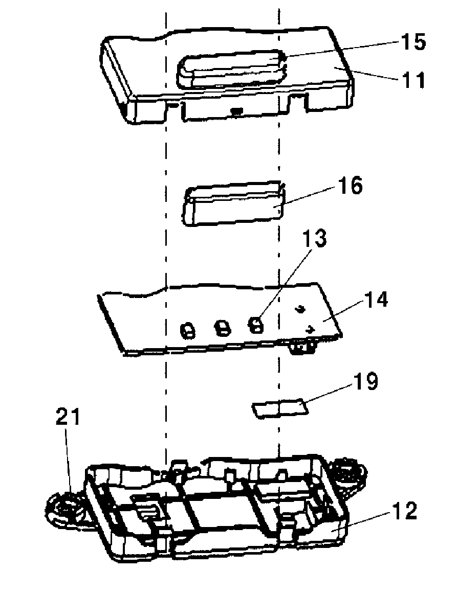
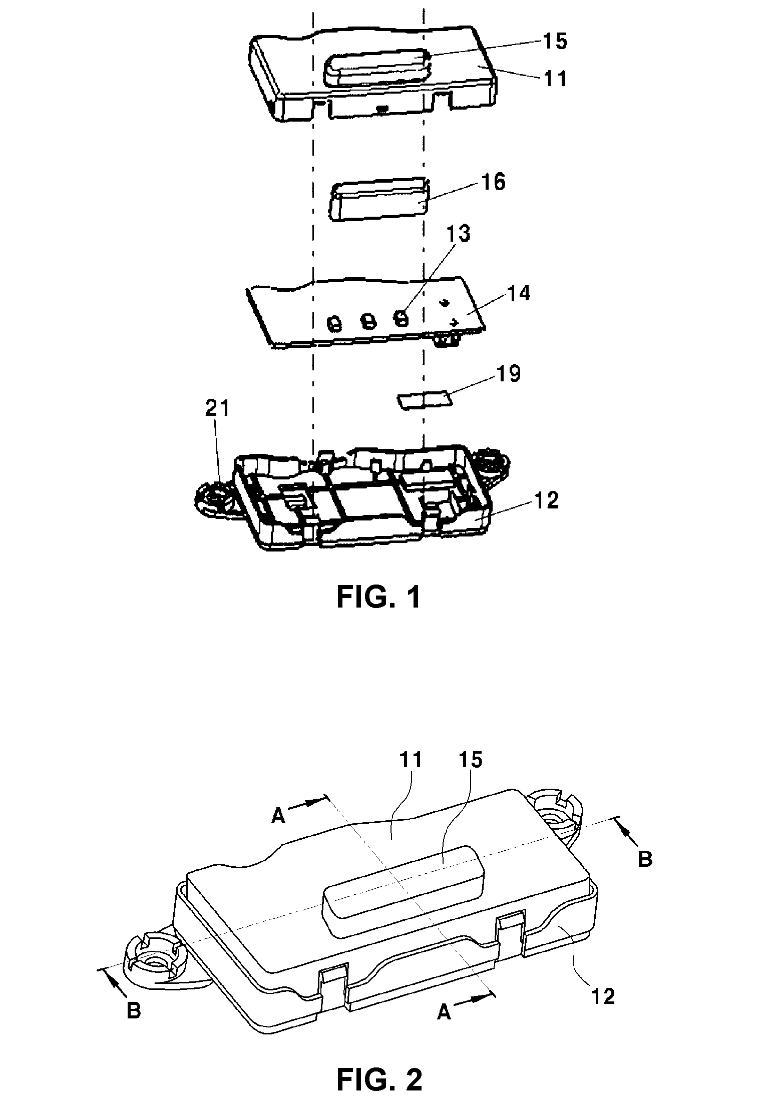
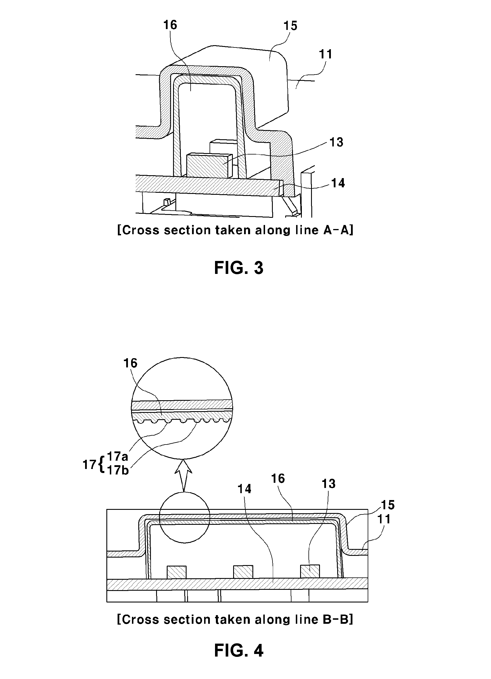
[0048]FIGS. 1 to 4 are perspective views and cross-sectional views illustrating a charging status indicator of an electric vehicle according to various embodiments of the present invention.

[0049]As illustrated in FIGS. 1 to 4, in order to solve non-uniformity of Light Emitting Diode (LED)-irradiated light which is projected to a l...


PUM


Abstract

A charging status indicator of an electric vehicle installed at one side of a charging status indicator cover to indicate a charging status of the electric vehicle as an illumination may include a lens-integrated lamp housing and a printed circuit board (PCB) housing which are vertically coupled to each other, a PCB installed in the PCB housing and having a plurality of Light Emitting Diodes (LEDs) mounted thereon, and a diffusion cap diffusing LED.

Description

CROSS-REFERENCE TO RELATED APPLICATION[0001]The present application claims priority to Korean Patent Application No. 10-2015-0017790 filed Feb. 5, 2015, the entire contents of which is incorporated herein for all purposes by this reference.BACKGROUND OF THE INVENTION[0002]1. Field of the Invention[0003]The present invention relates to a battery charging status indicator for an electric vehicle, and more particularly, to a battery charging status indicator for an electric vehicle which indicates a charging status of the electric vehicle by a lighting sequence of a plurality of indicator lenses or a color change of one indicator lens.[0004]2. Description of Related Art[0005]Generally, an electric vehicle includes a charging apparatus including a charging connector for charging a battery, a lamp for indicating whether the battery charging is completed, and the like.[0006]A charging complete indicator lamp is provided at a position where the charging connector exists, and generally conf...

Claims


Application Information

Patent Timeline
Patent Type & Authority Applications(United States)
IPC IPC(8): H02J7/00B60Q9/00
CPCH02J7/0047H02J2007/005B60Q9/00F21S43/14F21S43/26F21V19/001H02J7/0049B60L2250/16B60L58/12B60L50/64H02J7/0048H02J2310/48Y02T10/70Y02T90/10H01L21/00
Inventor WOO, JUNG HOONKIM, HEON CHEOL
Owner HYUNDAI MOTOR CO LTD
Learn More