In-wheel motor and in-wheel motor driving device

a technology of in-wheel motors and driving devices, which is applied in the direction of vehicle sub-unit features, magnetic circuit rotating parts, and shape/form/construction of magnetic circuits, etc., can solve the problems of high cost, inability to apply the technique of patent document 2 to the in-wheel motor, and instability of detection accuracy, so as to achieve the effect of reducing axial dimensions and low cos

Inactive Publication Date: 2016-08-11
NTN CORP
View PDF4 Cites 3 Cited by
  • Summary
  • Abstract
  • Description
  • Claims
  • Application Information

AI Technical Summary

Benefits of technology

[0012]An object of the present invention is to provide an in-wheel motor and an in-wheel motor driving device which have a rotational sensor in a motor housing and which enable an axial dimension to be reduced without an increase in a radial dimension and with low cost.

Problems solved by technology

In Patent Document 2, the sensor itself is enlarged, leading to high cost.
Further, a gap against the sensor changes due to a moment load and vibration of the vehicle, and the like, and as a result, the detection accuracy becomes unstable.
Therefore, the technique in Patent Document 2 is difficult to be applied to the in-wheel motor.

Method used


Image

  • In-wheel motor and in-wheel motor driving device
  • In-wheel motor and in-wheel motor driving device
  • In-wheel motor and in-wheel motor driving device

Examples


Embodiment Construction

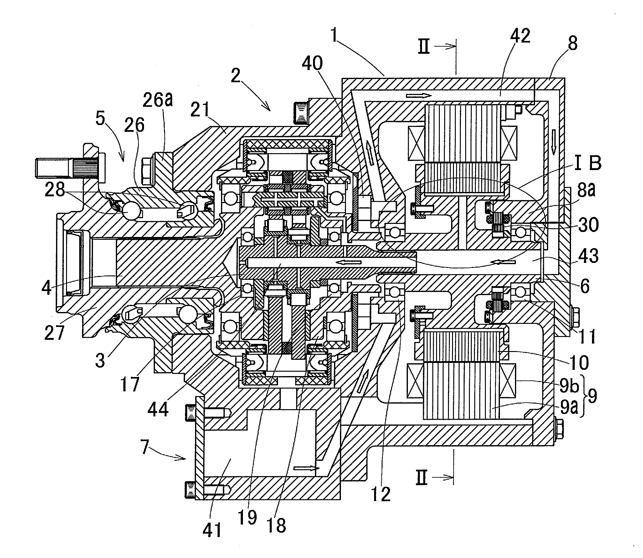
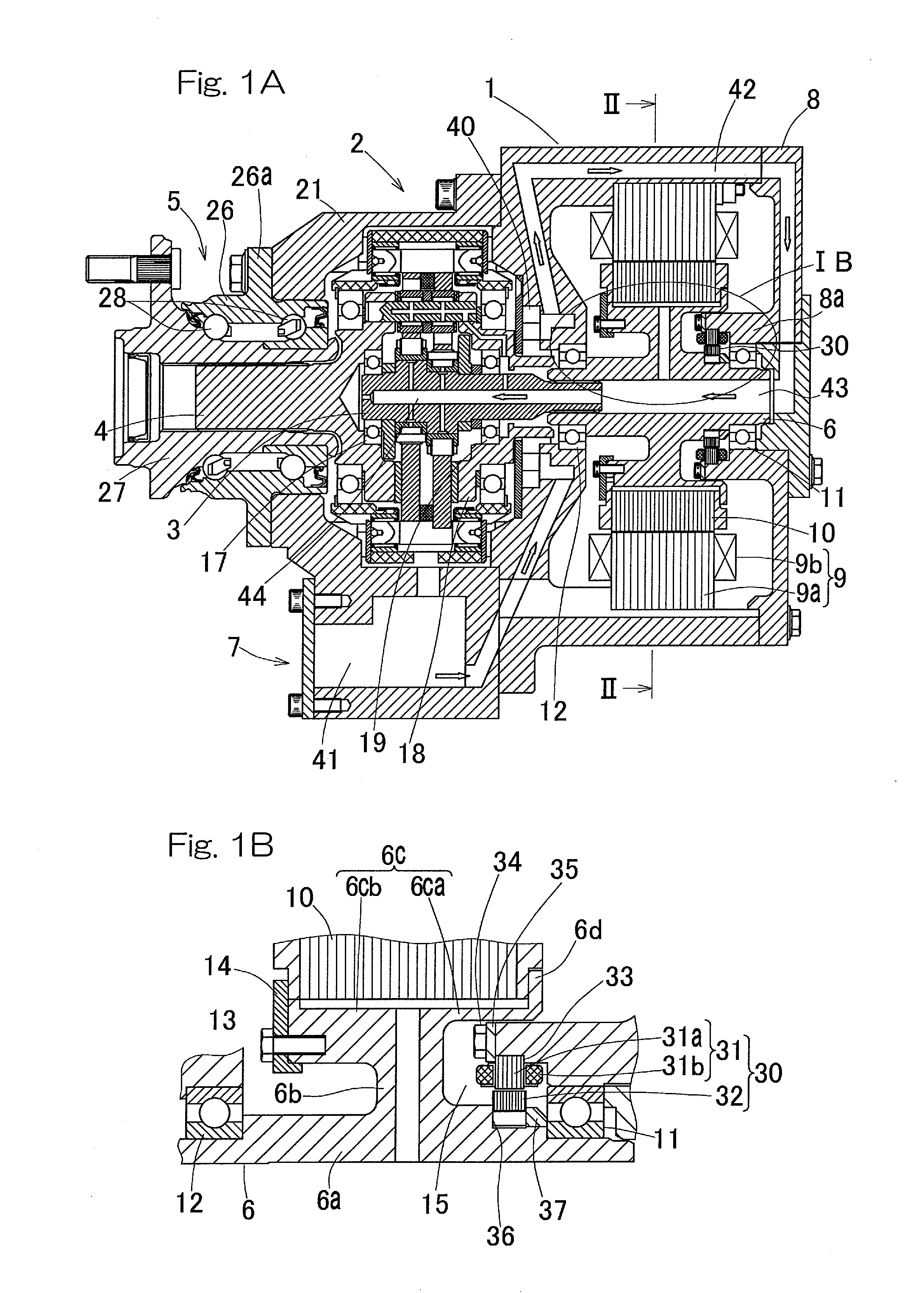
[0028]The embodiments of the present invention will be described with reference to the drawings. FIGS. 1A and 1B are sectional views of an in-wheel motor driving device having an in-wheel motor according to an embodiment of the present invention. The in-wheel motor driving device includes: an electric motor 1 which is an in-wheel motor for driving a wheel; a reducer or reduction gear 2 for reducing the speed of rotation of the electric motor 1; a wheel bearing 5 to be rotated by an output member 4 which is concentric with an input shaft 3 of the reducer 2; and a lubricating oil supply mechanism 7. The reducer 2 is interposed between the wheel bearing 5 and the electric motor 1, and a hub of the wheel which is a drive wheel supported by the wheel bearing 5 is coupled concentrically with a rotation shaft 6 of the electric motor 1.

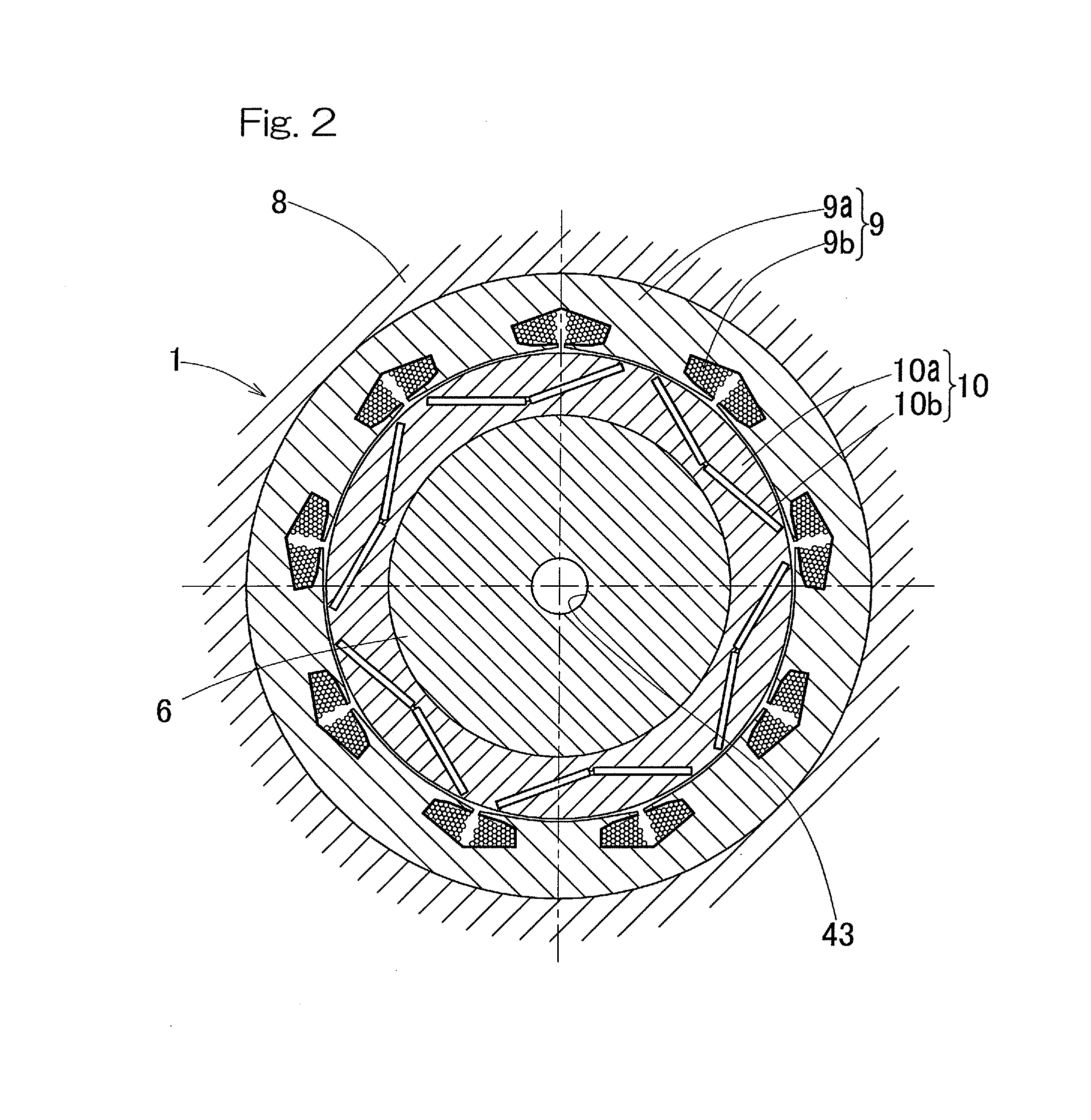
[0029]The electric motor 1 includes a motor stator 9 and a motor rotor 10 which are housed in a motor housing 8. As shown in FIG. 2, the motor stator 9 has a...


PUM


Abstract

An electric motor which is an in-wheel motor includes a motor housing, a motor stator, a rotation shaft, a motor rotor, and a rotational sensor. The rotation shaft has: a shaft portion rotatably supported by a plurality of bearings; a flange portion spreading toward the outer diameter side from the outer circumference of the shaft portion; and a cylindrical portion extending from the outer diameter end of the flange portion in parallel with the shaft portion, and having an outer circumference to which the motor rotor is fitted. The axial position of the rotational sensor is between the plurality of bearings, and the rotational sensor is provided on the inner diameter side of the cylindrical portion of the rotation shaft.

Description

CROSS REFERENCE TO THE RELATED APPLICATION[0001]This application is a continuation application, under 35 U.S.C. §111(a), of international application No. PCT / JP2014 / 077804, filed Oct. 20, 2014, which is based on and claims Convention priority to Japanese patent application No. 2013-224312, filed Oct. 29, 2013, the entire disclosure of which is herein incorporated by reference as a part of this application.BACKGROUND OF THE INVENTION[0002]1. Field of the Invention[0003]The present invention relates to an in-wheel motor used for a drive wheel of an electric vehicle, a hybrid electric vehicle, or the like, and to an in-wheel motor driving device having the in-wheel motor incorporated therein.[0004]2. Description of Related Art[0005]An in-wheel motor is provided together with a power transmission mechanism and the like in a limited space under a spring, or below a suspension device. Therefore, the axial dimension is desired to be as short as possible. An in-wheel motor is often combined...

Claims


Application Information

Patent Timeline
Patent Type & Authority Applications(United States)
IPC IPC(8): H02K7/14H02K9/19H02K1/27H02K7/116H02K11/225
CPCH02K1/28H02K7/006B60Y2306/03B60K7/0007B60K17/046B60K2007/0038Y02T10/641H02K1/27H02K7/116H02K7/14H02K9/19H02K11/225B60K2007/0092Y02T10/64
Inventor MAKINO, YUSUKESUZUKI, KENICHI
Owner NTN CORP
Why Eureka
Try Eureka