Hybrid vehicle

a hybrid vehicle technology, applied in the direction of propulsion parts, propulsion using engine-driven generators, transportation and packaging, etc., can solve the problem of restricting the charging of power storage devices, and achieve the effect of quick operation

Active Publication Date: 2016-08-18
TOYOTA JIDOSHA KK
View PDF10 Cites 19 Cited by
  • Summary
  • Abstract
  • Description
  • Claims
  • Application Information

AI Technical Summary

Benefits of technology

[0014]An object of this invention is to provide a hybrid vehicle that allows the engin...

Problems solved by technology

Moreover, through this control, charging of the power storage device can be restricted whi...

Method used


Image

  • Hybrid vehicle
  • Hybrid vehicle
  • Hybrid vehicle

Examples


first embodiment

[0056]In the first embodiment, a basic configuration and basic operation of a hybrid vehicle 1 will be described first with FIGS. 1 to 13, and then control and operation during an engine brake operation will be described with FIGS. 14 to 21.

[0057][Overall Configuration of Hybrid Vehicle]

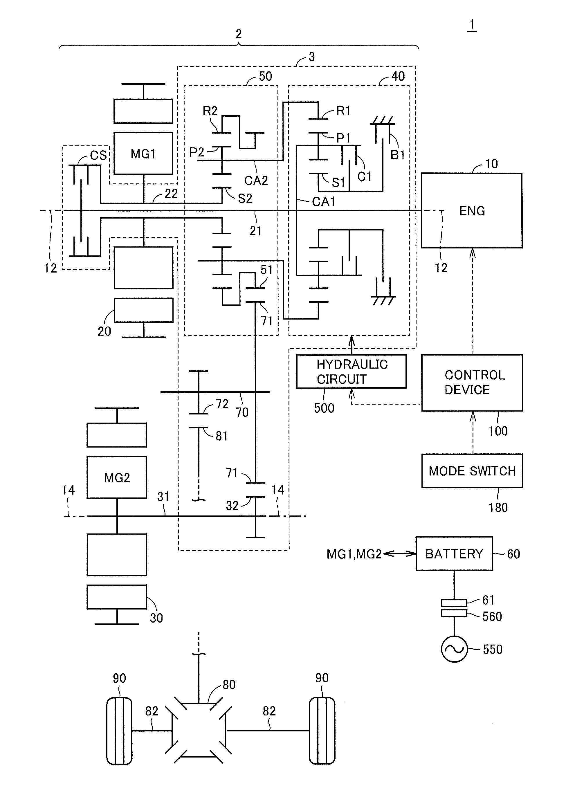
[0058]FIG. 1 is a diagram showing an overall configuration of a hybrid vehicle including a drive device according to the embodiment of this invention.

[0059]Referring to FIG. 1, hybrid vehicle 1 includes an engine 10, a drive device 2, driving wheels 90, and a control device 100. Drive device 2 includes a first motor generator (hereinafter referred to as “first MG”) 20, a second motor generator (hereinafter referred to as “second MG”) 30, a power transmission unit 3, a differential gear 80, a hydraulic circuit 500, and a battery 60. Power transmission unit 3 includes a transmission unit 40, a differential unit 50, a clutch CS, an input shaft 21, and an output shaft (counter shaft) 70.

[0060]Hybrid vehi...

second embodiment

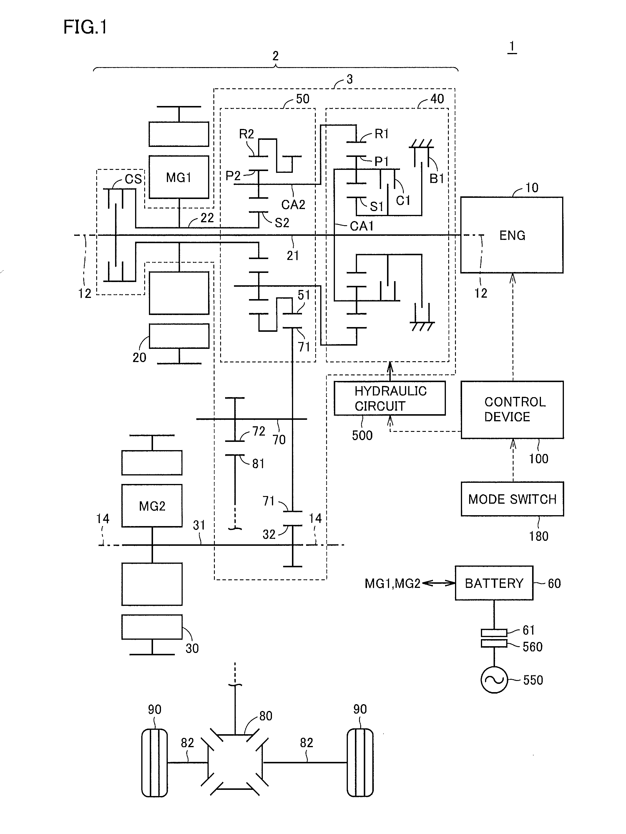
[0188]In the first embodiment, the case has been described where the standby operation for the engine brake is executed in the configuration as shown in FIG. 1 in which the two rotation shafts of first MG 20 and second MG 30 are arranged in parallel, and transmission unit 40 is connected to engine 10.

[0189]In the second embodiment, a case where the standby operation for the engine brake is executed in another configuration will be described.

[0190]FIG. 22 is a diagram showing the configuration of a hybrid vehicle 601 according to the second embodiment. In the configuration shown in FIG. 22, a portion symmetric with respect to rotation shaft 12A (lower half of the sheet) is omitted. FIG. 23 is a block diagram showing a power transmission path between various components of the vehicle in FIG. 22 in simplified form. Note that FIG. 22 is for comparison with FIG. 2. As shown in FIGS. 22 and 23, hybrid vehicle 601 includes engine 10, a first MG 20A, a second MG 30A, a power transmission un...


PUM


Abstract

A hybrid vehicle includes a power transmission unit configured to switch a power transmission path between an engine, a first MG, and a second MG. The control device is configured such that, during execution of regenerative braking using at least one of the first MG and the second MG while the engine is stopped, when a state amount indicating a state related to a battery has reached a determination threshold, the control device executes a standby operation in which the state of the power transmission unit is brought from a current state closer to a state that enables an engine brake operation in which the engine in a fuel-cut state is rotated using an external force to generate a loss.

Description

[0001]This nonprovisional application is based on Japanese Patent Application No. 2015-029437 filed on Feb. 18, 2015, with the Japan Patent Office, the entire contents of which are hereby incorporated by reference.BACKGROUND OF THE INVENTION[0002]1. Field of the Invention[0003]This invention relates to a hybrid vehicle, and particularly to a hybrid vehicle including first and second rotating electric machines and an internal combustion engine.[0004]2. Description of the Background Art[0005]A hybrid vehicle is known that is configured to include, in addition to an engine, two rotating electric machines and a power split device, a transmission mechanism between the engine and the power split device.[0006]The vehicle disclosed in WO2013 / 114594 adopts a series / parallel hybrid system. In the vehicle using the series / parallel hybrid system, motive power of the engine is transmitted to a first motor generator (first MG) to be used for generating electric power, while part of the motive pow...

Claims


Application Information

Patent Timeline
IPC IPC(8): B60W20/14B60W10/06B60W10/08B60W10/10B60K6/543B60K6/387B60K6/442B60K6/445B60K6/26B60W20/20B60K6/365B60L50/15B60L50/16
CPCB60W20/14Y10S903/919B60W10/06B60W10/08B60W10/10B60K6/365B60K6/387B60K6/442B60K6/445B60K6/26B60K6/543B60W2540/12B60W2540/10B60W2520/10B60W2510/081B60W2510/104B60W2510/244B60W2710/0605B60W2710/0616B60W2710/083B60W2710/021B60Y2200/92Y10S903/93Y10S903/906Y10S903/911Y10S903/914B60W20/20B60W40/00B60W40/105B60W40/107B60W2510/08B60W2510/087B60W2510/1005B60W2510/107B60W2510/246B60W2520/105B60W2710/0666B60W10/115B60W30/18127Y02T10/62Y02T10/92Y02T10/70Y02T10/7072
Inventor IMAMURA, TATSUYATABATA, ATSUSHIKANADA, TOSHIKIBANSHOYA, HIDEHIKO
Owner TOYOTA JIDOSHA KK
Why Eureka
Try Eureka