Drill Pipe Oscillation Regime and Torque Controller for Slide Drilling

a technology of oscillation regime and torque controller, which is applied in the direction of directional drilling, rotary drilling, percussion drilling, etc., can solve the problems of drilling operators under-utilizing the oscillation feature, the drill string near the bit may slip relative to the wellbore side at a high (and often damaging) speed, and undesirable resonance motion between the top drive and the bha

a technology of oscillation regime and torque controller, which is applied in the direction of directional drilling, rotary drilling, percussion drilling, etc., can solve the problems of drilling operators under-utilizing the oscillation feature, the drill string near the bit may slip relative to the wellbore side at a high (and often damaging) speed, and undesirable resonance motion between the top drive and the bha

US20160237802A1Active Publication Date: 2016-08-18NABORS DRILLING TECH USA INC

Image

  • Drill Pipe Oscillation Regime and Torque Controller for Slide Drilling
  • Drill Pipe Oscillation Regime and Torque Controller for Slide Drilling
  • Drill Pipe Oscillation Regime and Torque Controller for Slide Drilling

Examples


Embodiment Construction

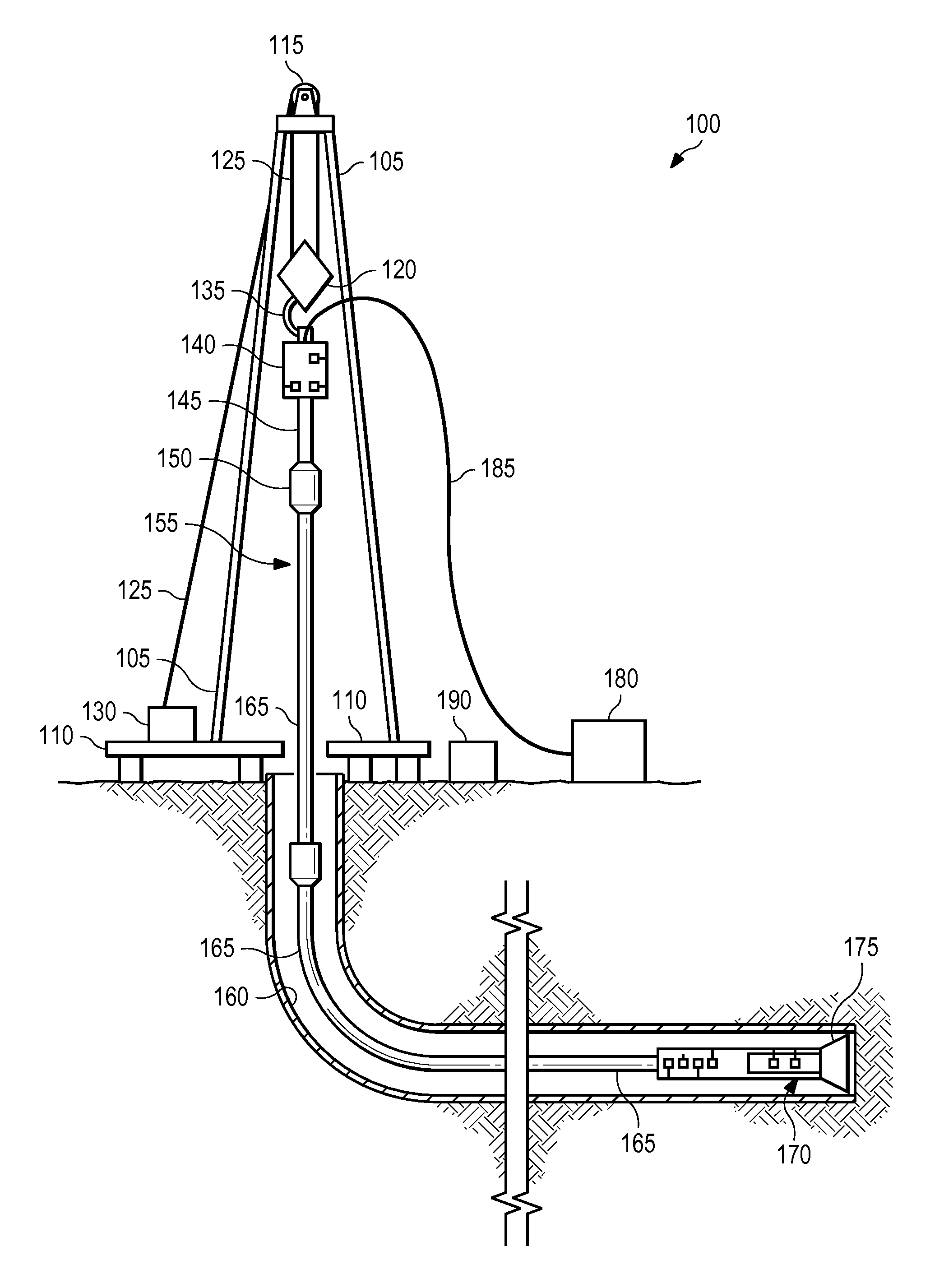
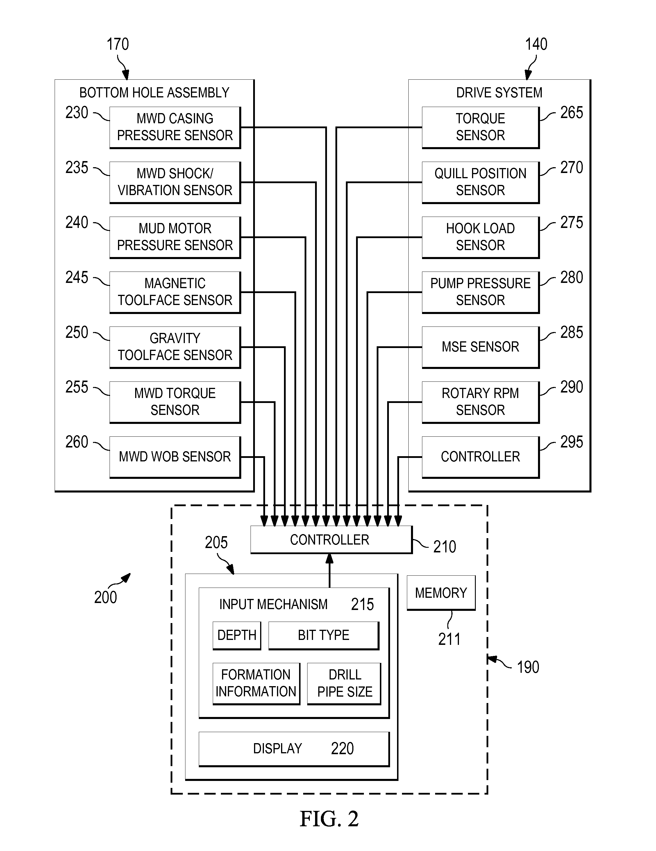
[0013]It is to be understood that the following disclosure provides many different embodiments, or examples, for implementing different features of various embodiments. Specific examples of components and arrangements are described below to simplify the present disclosure. These are, of course, merely examples and are not intended to be limiting. In addition, the present disclosure may repeat reference numerals and / or letters in the various examples. This repetition is for the purpose of simplicity and clarity and does not in itself dictate a relationship between the various embodiments and / or configurations discussed. Moreover, the formation of a first feature over or on a second feature in the description that follows may include embodiments in which the first and second features are formed in direct contact, and may also include embodiments in which additional features may be formed interposing the first and second features, such that the first and second features may not be in d...


PUM


Abstract

Apparatuses, methods, and systems are described which assist in controlling toolface orientation of a bottom hole assembly. A controller instructs a top drive to oscillate a drill string an oscillation revolution amount to reduce friction of the drill string in a wellbore during a slide drilling procedure. A torque sensor detects torque at an interface between the drill string and the top drive, and the controller determines properties of a torsional wave from the detected torque that is propagating along the drill string during the slide drilling procedure. The controller determines a modification to the oscillation revolution amount and / or rotations per minute in order to control the toolface orientation in a desired manner. The top drive implements the determined modification and thereby assists in controlling the toolface orientation during the slide drilling procedure.

Description

BACKGROUND OF THE DISCLOSURE[0001]Underground drilling involves drilling a bore through a formation deep in the Earth using a drill bit connected to a drill string. Two common drilling methods, often used within the same hole, include rotary drilling and slide drilling. Rotary drilling typically includes rotating the drilling string, including the drill bit at the end of the drill string, and driving it forward through subterranean formations. This rotation often occurs via a top drive or other rotary drive means at the surface, and as such, the entire drill string rotates to drive the bit. This is often used during straight runs, where the objective is to advance the bit in a substantially straight direction through the formation.[0002]During rotary drilling, the rotational force applied at the top drive is often out of phase with the reaction at the bottom-hole assembly (BHA) of the drill string due to an elasticity of the material of the drill string, causing the drill string to ...

Claims


Application Information

Patent Timeline
18 Aug 2016
Publication
US20160237802A1
IPC
E21B44/04; E21B7/06; E21B3/02
CPC
E21B44/04; E21B7/06; E21B3/02; E21B7/04; E21B44/00
Inventors
BOONE, SCOTT G.; GILLAN, COLIN J.