Permanent-magnet synchronous motor torque control system and method based on a sliding-mode observer and auto-disturbance rejection control
A technology of permanent magnet synchronous motor and sliding mode observer, which is applied in the direction of control system, control generator, vector control system, etc., and can solve problems such as difficult to meet the dynamic performance of the current loop, integral saturation, etc.
- Summary
- Abstract
- Description
- Claims
- Application Information
AI Technical Summary
Problems solved by technology
Method used
Image
Examples
Embodiment 1
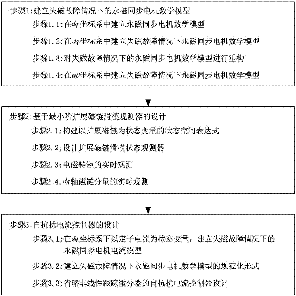
[0051] The execution subject of the permanent magnet synchronous motor torque control method in this embodiment is a sliding mode observer and an active disturbance rejection current controller, figure 1 It is a schematic flowchart of a method for controlling the torque of a permanent magnet synchronous motor based on a sliding mode observer and active disturbance rejection control according to Embodiment 1 of the present invention. like figure 1 As shown, this embodiment provides a permanent magnet synchronous motor torque control method based on a sliding mode observer and active disturbance rejection control. The method is based on a permanent magnet synchronous motor control system, including:
[0052] Step 1, establishing the mathematical model of the permanent magnet synchronous motor under the condition of demagnetization fault;
[0053] Step 2, designing a sliding mode observer based on minimum order extended flux linkage;
[0054] Step 3, design ADRC current control...
Embodiment 2
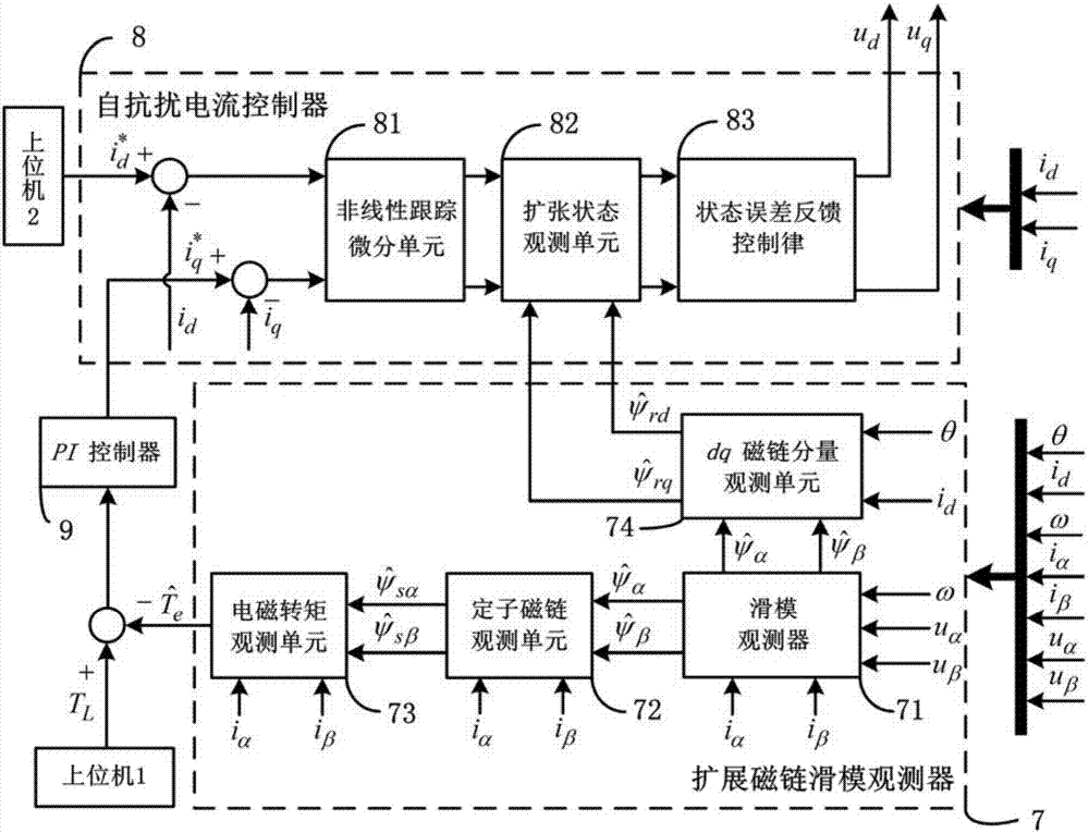
[0080] figure 2 It is a schematic diagram of the principle of the permanent magnet synchronous motor torque control system based on the sliding mode observer and active disturbance rejection control according to the second embodiment of the present invention, as figure 2 As shown, the system includes: extended flux linkage sliding mode observer 7, active disturbance rejection current controller 8, PI controller 9, upper computer 1, upper computer 2; the input terminals of active disturbance rejection current controller 8 are respectively connected with The output end of the extended flux linkage sliding mode observer 7, the output end of the upper computer 2, and the output end of the PI controller 9 are connected, and the input end of the PI controller 9 is connected with the output end of the upper computer 1 and the extended flux linkage sliding mode observer 7's output connection.
[0081] Described extended flux linkage sliding mode observer 7 comprises: sliding mode o...
Embodiment 3
[0092] This embodiment is a supplementary description based on the first embodiment.
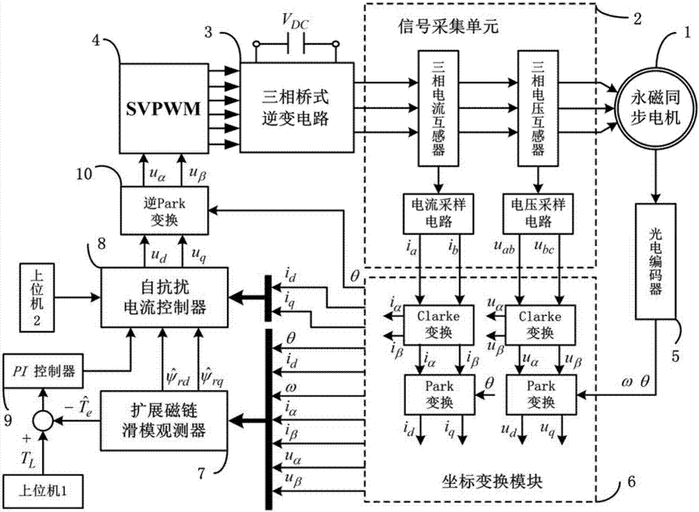
[0093] image 3 According to the schematic diagram of the system structure of Embodiment 2 of the present invention, in order to realize the system, it also needs: permanent magnet synchronous motor 1, signal acquisition unit 2, three-phase bridge inverter circuit 3, SVPWM module 4, photoelectric encoder 5, Coordinate transformation module 6, inverse Park transformation module 10; The output end of coordinate transformation module 6 is respectively connected with the input end of extended flux linkage sliding mode observer 7, the input end of active disturbance rejection current controller 8, and the input of inverse Park transformation module 10 terminal connection, the output end of the inverse Park transformation module 10 is connected with the input end of the SVPWM module 4, the output end of the SVPWM module 4 is connected with the input end of the three-phase bridge inverter circuit 3...
PUM
 Abstract
Description
Claims
Application Information
 - R&D
- Intellectual Property
- Life Sciences
- Materials
- Tech Scout
- Unparalleled Data Quality
- Higher Quality Content
- 60% Fewer Hallucinations
Browse by: Latest US Patents, China's latest patents, Technical Efficacy Thesaurus, Application Domain, Technology Topic, Popular Technical Reports.
© 2025 PatSnap. All rights reserved.Legal|Privacy policy|Modern Slavery Act Transparency Statement|Sitemap|About US| Contact US: help@patsnap.com


