Velocity compensation control for electric steering systems

a technology of velocity compensation and electric steering, which is applied in the direction of steering initiation, instruments, vessel construction, etc., can solve the problems of increasing high frequency disturbance sensitivity, difficult to apply a control architecture, and no effective way

Inactive Publication Date: 2004-08-19
GM GLOBAL TECH OPERATIONS LLC +1
View PDF99 Cites 32 Cited by
  • Summary
  • Abstract
  • Description
  • Claims
  • Application Information

AI Technical Summary

Benefits of technology

0017] FIG. 9 is a block diagram depicting an alternate control structure with motor velocity compensation.

Problems solved by technology

While well suited for its intended purposes, this system may be sensitive to motor velocity disturbances and there is no effective way of rejecting them in present structure because the compensation is in the torque path.
With the aforementioned considerations, it has been difficult to apply a control architecture such as that depicted in FIG. 1 to some vehicles and tune the control system to achieve acceptable performance.
Excessive high-pass gains 104 may be needed to improve the disturbance rejection at lower frequencies, which unfortunately, increases high frequency disturbance sensitivity.
In fact, there may be instances where high-frequency disturbances may not be completely rejected with any stable tuning employed.

Method used


Image

  • Velocity compensation control for electric steering systems
  • Velocity compensation control for electric steering systems
  • Velocity compensation control for electric steering systems

Examples


Embodiment Construction

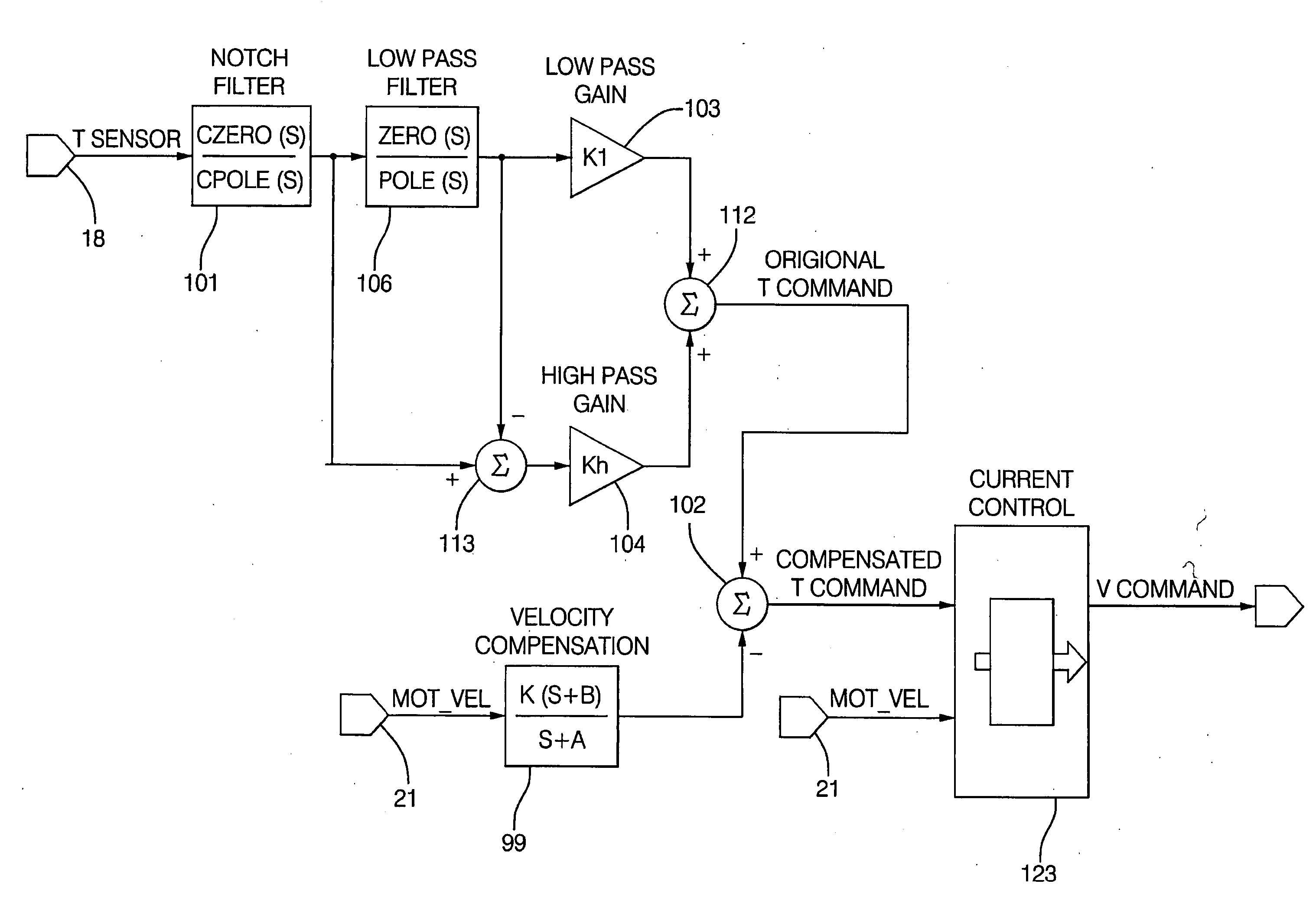
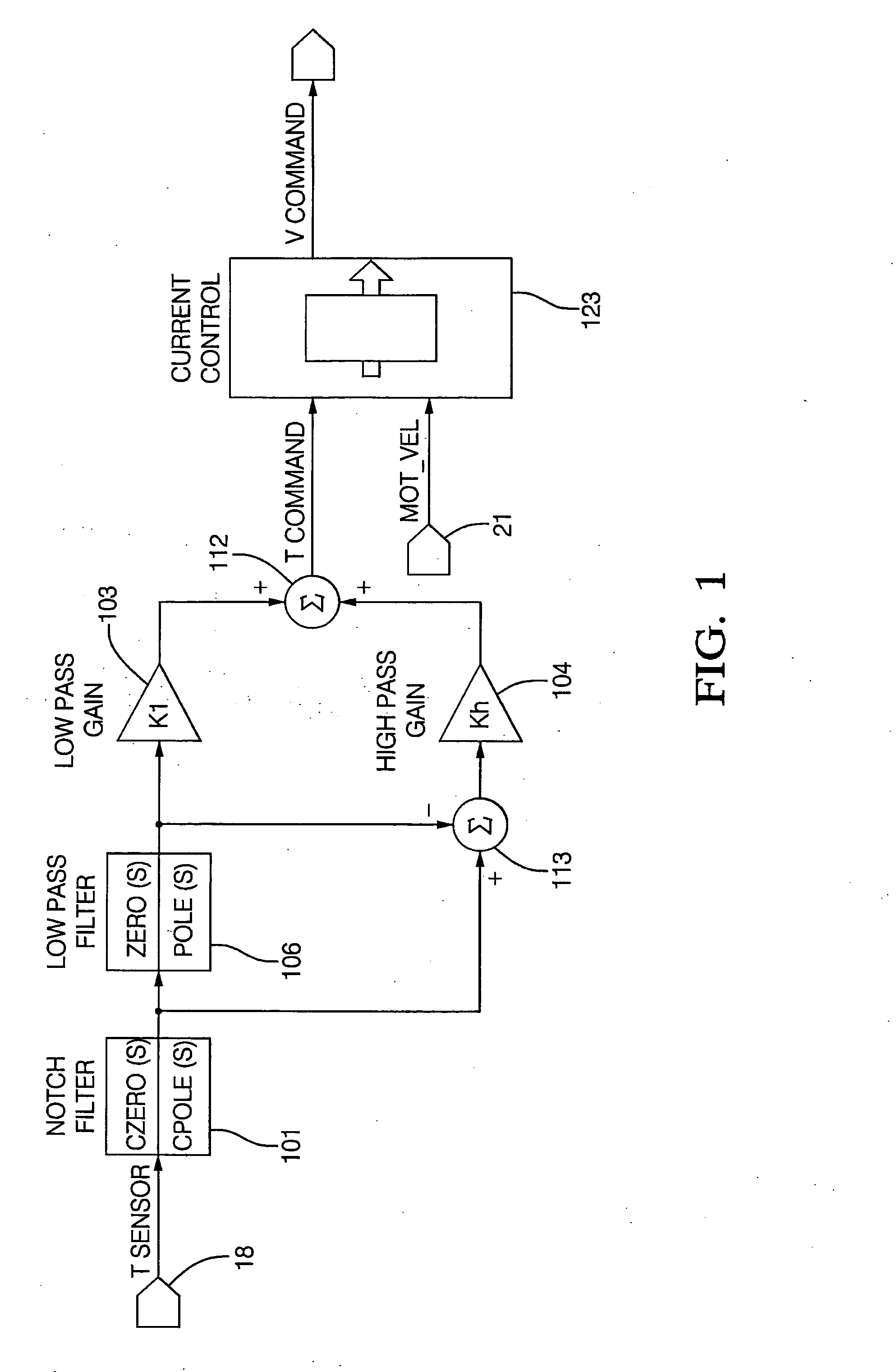
[0018] Electric power systems which utilize forward path motor BEMF compensation are more sensitive to motor velocity disturbances. One approach to address and control the ill effects of high frequency disturbances is to eliminate the source of the disturbance. The other approach is to reduce sensitivity of the EPS system to high frequency disturbances by changing the control strategy or architecture. The disclosed embodiments address the latter.

[0019] Generally, lower frequency torque compensators e.g., notch filters have to be deeper to provide the same stability margin as a higher frequency torque compensator. It should be appreciated that deeper notch filters (e.g., those exhibiting more gain reduction at the notch frequency) while providing necessary stability degrade the disturbance rejection properties of the system at the notch frequency. Further, it should be recognized that a closed loop system cannot reject disturbances where the gain is very low, as it is at the notch ce...


PUM


Abstract

Disclosed herein is a method as well as a system for controlling an electric power steering system. The method includes: receiving a torque signal from a torque sensor responsive to a torque applied to a steering wheel; obtaining a motor velocity signal, the motor velocity signal indicative of a speed of an electric motor which applies torque to a steerable wheel; and generating a command for said electric motor with a controller coupled to the torque sensor, and the electric motor. The command includes torque control and motor velocity compensation, responsive to at least one of the torque signal, and a motor velocity signal. Also disclosed herein is a storage medium encoded with a computer program code for controlling an electric power steering system, the storage medium includes instructions for causing controller to implement the disclosed method. Further disclosed is a computer data signal for controlling an electric power steering system, the data signal comprising code configured to cause a controller to implement the disclosed method. Additionally, a method for optimizing controlling torque in an electric power steering system is disclosed. The method including: receiving a torque signal responsive to a torque applied to a steering wheel; obtaining a motor velocity; generating a command with a controller for the electric motor, where the command includes a torque control and motor velocity compensation, responsive to the torque signal, and the motor velocity. The performance of the torque control is responsive to a torque compensator, a high pass low pass structure, and motor velocity compensation.

Description

[0001] This application claims the benefit of U.S. provisional application No. 60 / 297,066, filed Jun. 08, 2001 the contents of which are incorporated by reference herein in their entirety.[0002] Existing compensation structures for Electric Power Steering (EPS) systems often use torque loop compensation for an electric motor control system without motor velocity compensation. As shown in FIG. 1, in such an existing EPS system employing voltage mode control, a torque compensator 101 commonly a notch filter is employed in the torque path to provide phase lead to ensure that the system remains stable. Since the motor (46 FIG. 2) is run in voltage (pseudo current) mode, back electromotive force (BEMF) compensation proportional to the measured motor speed is added to the voltage command.[0003] Such an EPS system is disclosed and described in commonly assigned U.S. Pat. No. 5,719,766 to Bolourchi et al. While well suited for its intended purposes, this system may be sensitive to motor vel...

Claims


Application Information

Patent Timeline
Patent Type & Authority Applications(United States)
IPC IPC(8): B62D5/04B62D6/00B62D101/00B62D113/00B62D119/00B62D137/00H02P29/00
CPCB62D5/0472B62D5/0463
Inventor PATANKAR, RAVINDRA P.
Owner GM GLOBAL TECH OPERATIONS LLC
Why Eureka
Try Eureka