
System and method for a rangefinding instrument incorporating pulse and continuous wave signal generating and processing techniques for increased distance measurement accuracy

a technology of distance measurement accuracy and system and method, which is applied in the field of laser rangefinders and rangefinding instruments, can solve the problems of increasing complexity, unambiguous range of instruments, and increasing complexity of timing circuits, and achieves simple circuit implementation, effective solving ambiguity issues, and increased distance measurement accuracy

Active Publication Date: 2016-08-18
LASER TECH INC +1
View PDF2 Cites 1 Cited by
  • Summary
  • Abstract
  • Description
  • Claims
  • Application Information

AI Technical Summary

Benefits of technology

This patent describes a system and method for a rangefinding instrument that uses both pulse and continuous wave signal generating and processing techniques to improve distance measurement accuracy. This method helps to overcome the ambiguity issues that can occur with continuous wave ranging and allows for simpler circuit designs. This system can provide a more accurate measurement of distance based on phase, even when the target is not easily visible or discriminable. Additionally, this system can provide a warning flag to the user if the current accuracy of the phase-based system is not high.

Problems solved by technology

Among the disadvantages of such pulse-based devices is that, in order to achieve high levels of accuracy, rather complicated timing circuitry is required in addition to ensuring that the device remains properly calibrated for the then current operating conditions.
However, among the difficulties inherent in implementations of such phase-based systems is that the unambiguous range of the instrument is the period of the CW signal divided by two.
All of these solutions require ever more complicated circuitry and the problem they attempt to solve becomes increasingly more difficult to address as the distance from the target increases.
On the other hand, in phase-based systems the phase return is the vector sum of the backscatter from the target and the interfering dust or other object and there is no easy way of discriminating between the two.

Method used


Image

  • System and method for a rangefinding instrument incorporating pulse and continuous wave signal generating and processing techniques for increased distance measurement accuracy
  • System and method for a rangefinding instrument incorporating pulse and continuous wave signal generating and processing techniques for increased distance measurement accuracy
  • System and method for a rangefinding instrument incorporating pulse and continuous wave signal generating and processing techniques for increased distance measurement accuracy

Examples


Embodiment Construction

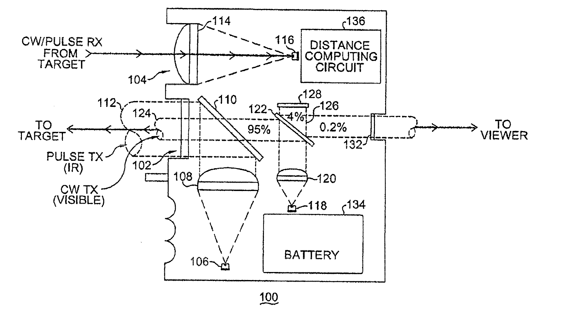
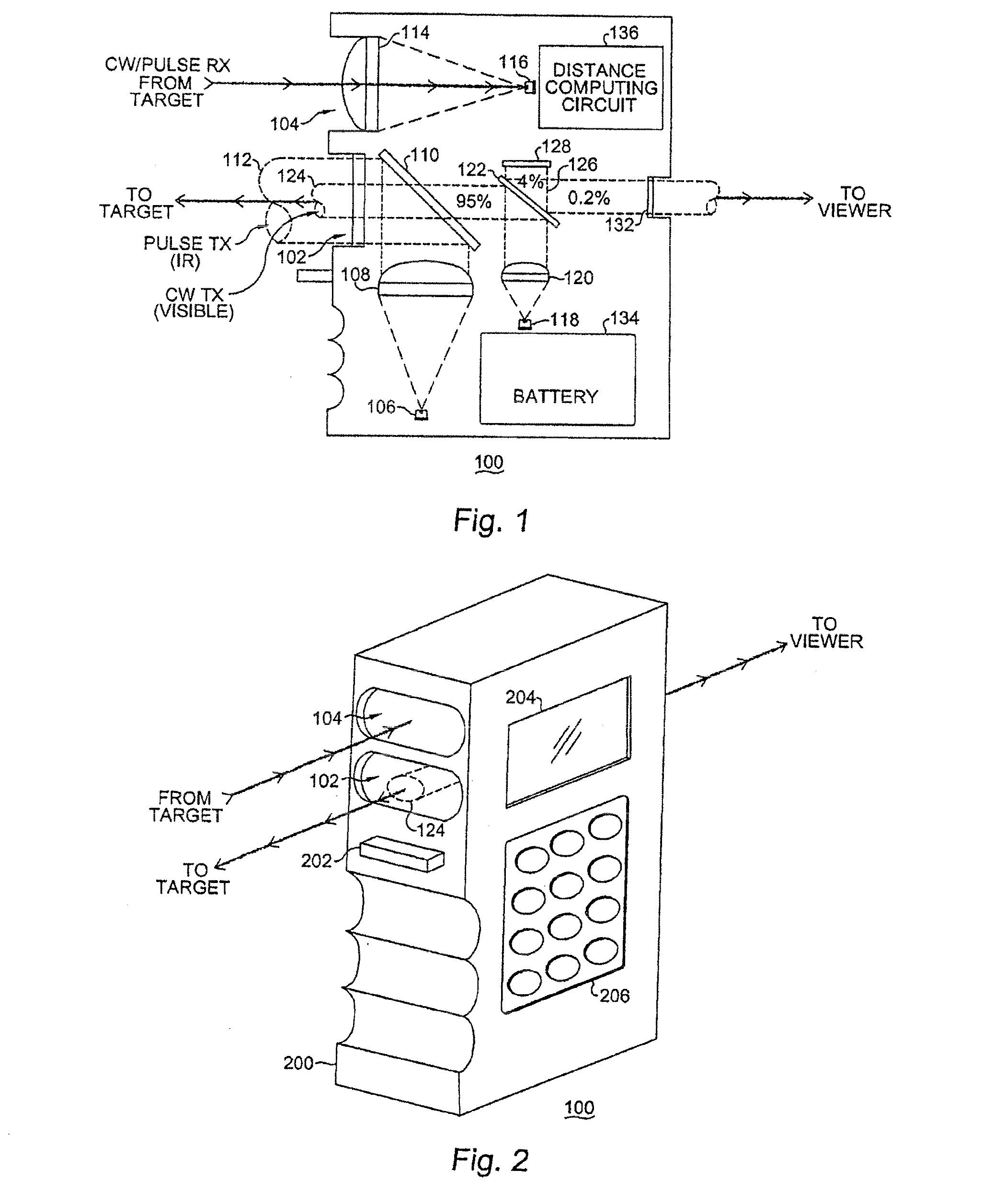
[0023]With reference now to FIG. 1, a simplified illustration of the optical and signal paths of a representative embodiment of the system and method of the present invention is shown in the form of a pulse-based and phase-based rangefinding instrument 100. The system and method of the present invention is operative to increase distance measurement accuracy in a rangefinding instrument by incorporating pulse and continuous wave signal generating and processing techniques.

[0024]The instrument 100, in pertinent part, comprises a pulsed laser beam and phase-based (CW) optical signal transmission aperture 102 and a reflected pulsed laser beam and continuous wave signal reception aperture 104, the latter for reception of both pulse-based and phase-based signals transmitted to a selected target from the transmission aperture 102 and reflected back to the instrument 100 from a target. The laser transmission system of the instrument 100 comprises a laser emitting diode 106 (or other similar...


PUM


Abstract

A system and method for a rangefinding instrument incorporating pulse and continuous wave signal generating and processing techniques for increased distance measurement accuracy. The use of the former technique effectively solves the ambiguity issues inherent in the latter while allowing for relatively simple circuit implementations. Thus, a potentially more accurate phase-based distance measurement technique can be utilized which is also completely independent of the maximum range to the target.

Description

CROSS REFERENCE TO RELATED PATENT APPLICATIONS[0001]The present invention claims priority from, and is a continuation of U.S. patent application Ser. No. 13 / 615,143 filed on Sep. 13, 2012, and is related to the subject matter disclosed in U.S. patent application Ser. No. 13 / 615,172 for: “System and Method for Superimposing a Virtual Aiming Mechanism with a Projected System Beam in a Compact Laser-Based Rangefinding Instrument” and Ser. No. 13 / 615,215 for: “Self-Aligned Aiming System and Technique for a Laser Rangefinder Incorporating a Retroreflector” both assigned to the assignees hereof and filed on even date herewith, the disclosures of which are herein specifically incorporated by this reference in their entirety.BACKGROUND OF THE INVENTION[0002]The present invention relates, in general, to the field of laser rangefinders and rangefinding instruments. More particularly, the present invention relates to a system and method for a rangefinding instrument incorporating pulse and con...

Claims


Application Information

Patent Timeline
Patent Type & Authority Applications(United States)
IPC IPC(8): G01S7/481G01S17/10G01S17/36G01S7/497G01S17/14
CPCG01S17/105G01S17/36G01C15/002G01S17/10G01S7/4802G01S7/4815G01S7/497G01C3/08G01S17/14
Inventor DUNNE, JEREMY G.FRISCHMAN, MARK
Owner LASER TECH INC
Learn More