Hybrid nuclear-hydro power plant

Inactive Publication Date: 2016-08-18
MCDANIEL ROBIN JERRY
View PDF2 Cites 0 Cited by
  • Summary
  • Abstract
  • Description
  • Claims
  • Application Information

AI Technical Summary

Benefits of technology

The patent introduces a new concept to maximize the use of existing hydro-power plants without compromising the use of water resources. This is accomplished by recycling the tail water from the plant using a collection pond and pumps directly connected to a nuclear reactor. The reactor does not need to generate electricity, but the heat from it can be directly utilized to generate pumping power to lift water. This design reduces concerns about balancing water demands and allows for easy operation and licensing. Intrinsically safe nuclear reactors, such as the Bi-Stable reactor, are ideal for this application due to their simplified design and lower costs.

Problems solved by technology

Many such dams are underutilized with seasonal variation as inflow deficit limits the availability of water as potential energy.
Recent analytical modeling of water availability and prediction of other water usages are a complex and developing science.
Many problems associated with the current methods of creating energy to lift water in such systems exist.
The electricity used to lift the stored water may or may not be locally generated or may not be naturally dependable or reliable as in the case of solar or wind power.
As the efficiency in each step is less than unity, therefor the multiplication of all the conversion factors leads to unavoidable losses.
Some previous inventions include heat sources that utilize combustion of fossil fuels, yet the main problem with that approach is the production of combustion gasses including large amounts of carbon dioxide and other pollutants.
This overly complicates the design, licensing, and operations of such power plants, and does not avoid the multiple step conversion power losses.

Method used


Image

  • Hybrid nuclear-hydro power plant
  • Hybrid nuclear-hydro power plant
  • Hybrid nuclear-hydro power plant

Examples


Embodiment Construction

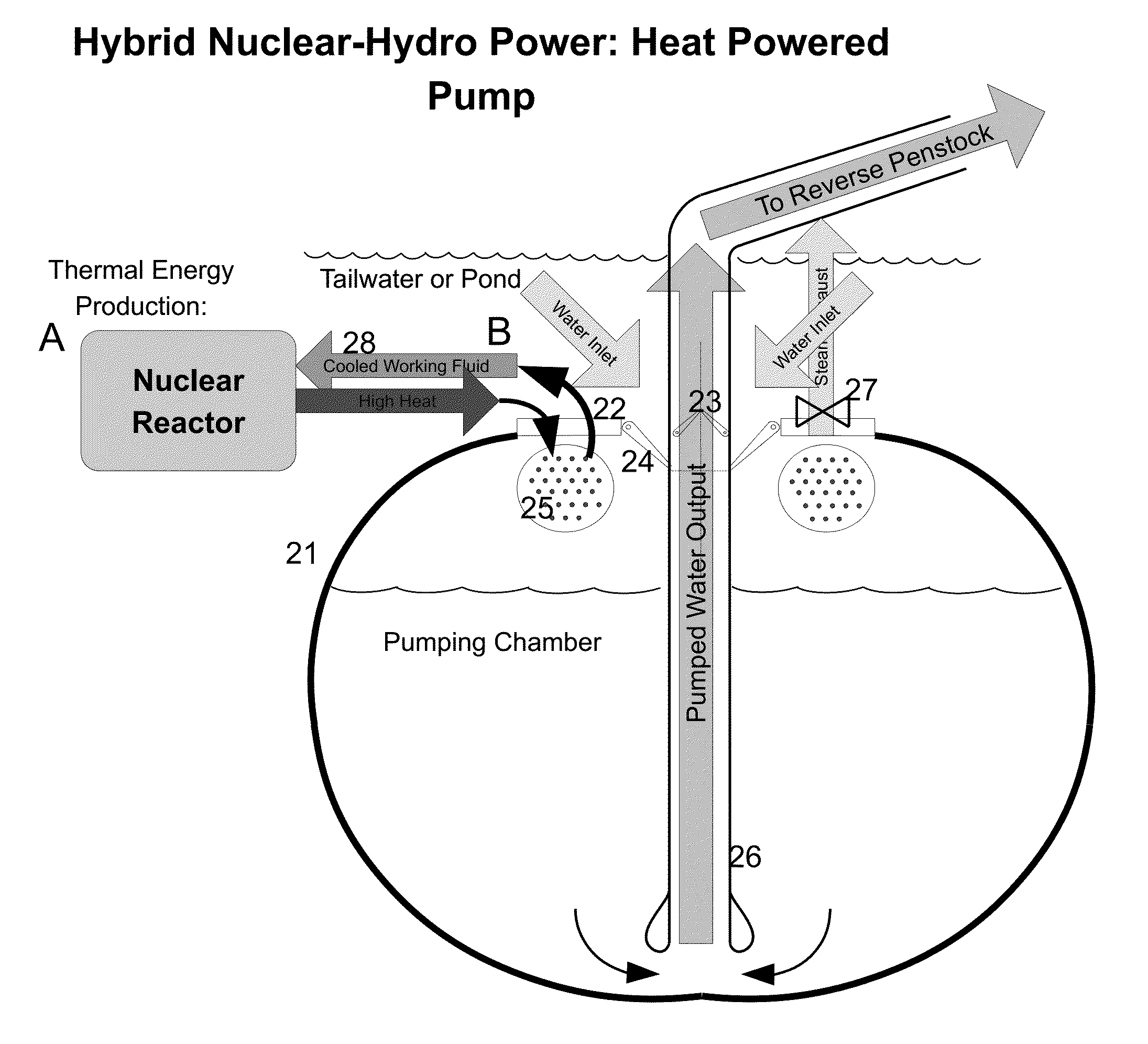
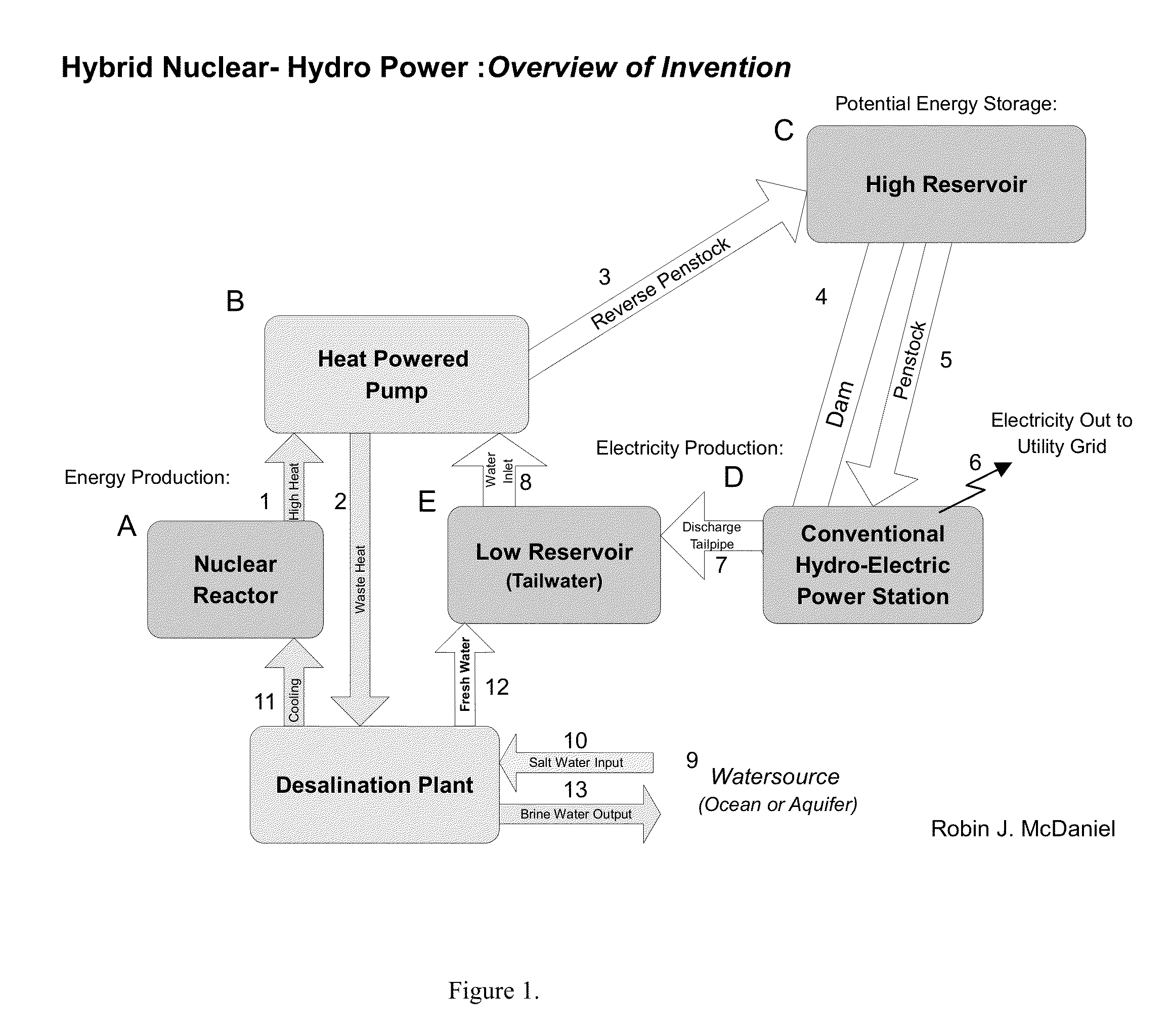
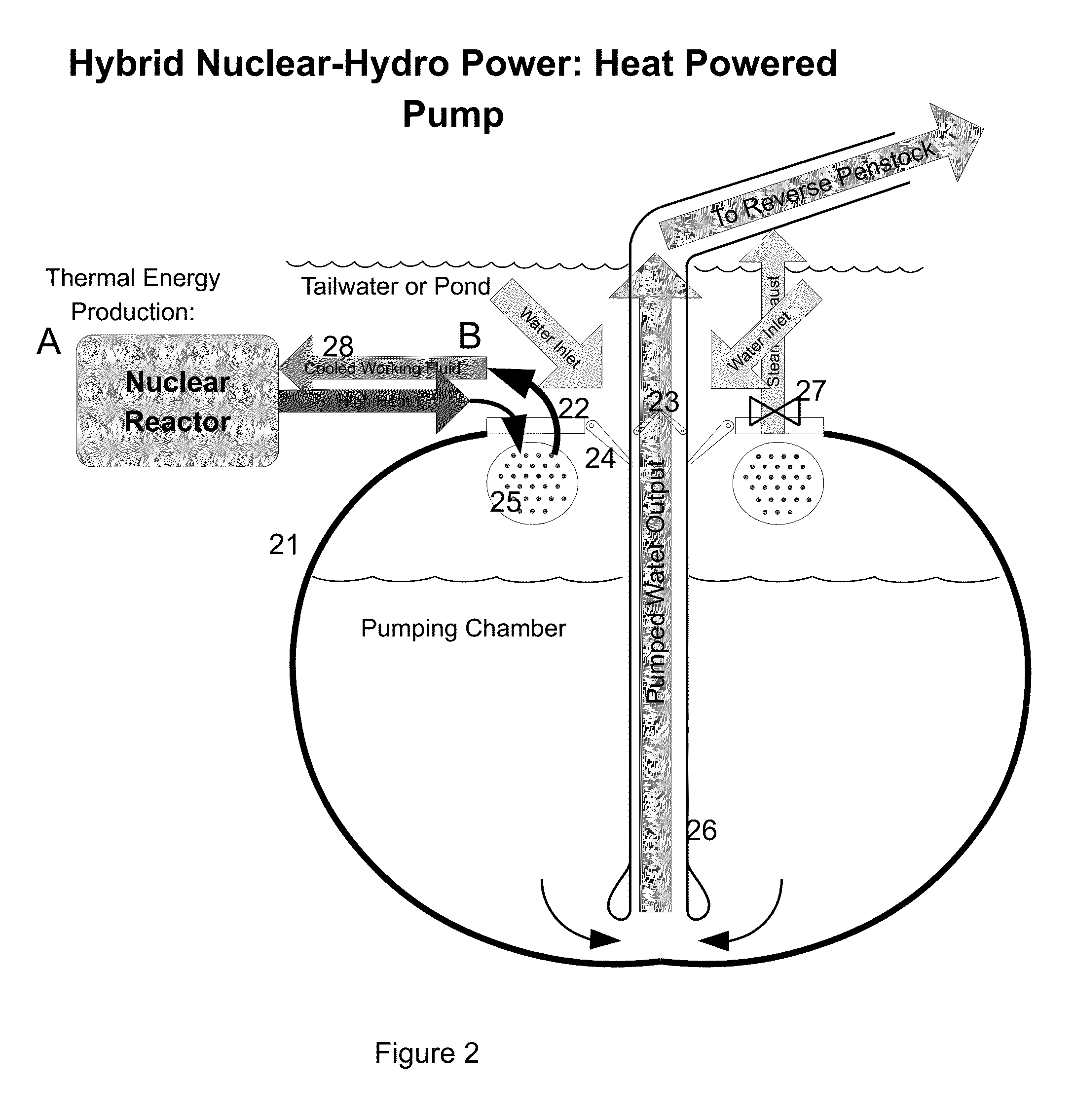
[0050]Referring now to FIG. 1: “Overview of Invention”, one embodiment of an Hybrid Nuclear-Hydro Power Plant may comprise a Nuclear Reactor A to provide heat to a Heat-Powered Pump B which takes water from a Low Reservoir E and lifts the water to a High Reservoir C where a Hydro-Electric Power Station D uses the potential energy of the reservoir to generate electricity. In one embodiment of a Hybrid Nuclear-Hydro Power Plant may utilize the waste heat from the Heat-Powered Pump B to provide low-value heat to a Desalination Plant, thus returning the coolant back to the Nuclear Reactor A after making fresh water, which may be deposited into the Low Reservoir E or otherwise distributed.

[0051]When the Nuclear Reactor A is turned on, and sufficient heat is achieved, a conduit 1 conveys the high value heat to a Heat Powered Pump B, which utilized inlet water 8 from the Low Reservoir E, via a created difference in pressure, lifting the water through a Reverse Penstock 3 into the High Rese...


PUM


Abstract

An improved electrical generation system explained herein is a method and equipment whereby nuclear reactors are used to directly propel water pumps to lift water from a lower-elevation body of water to a higher-elevation body of water, where it is stored as potential energy.In one application of this method, one or more water pumps, each powered directly by heat from a nuclear reactor, lift water from down-stream of a river, stream, or pond to upstream of a dam at which a hydro-power plant is installed. The nuclear reactor may be of the pressurized-water, boiling-water, liquid metal cooled, or molten salt-cooled type. Small modular reactors (SMRs) are ideally suited to provide pumping heat in an incremental manner in such a method. Reactor heat output may be proportionally diverted to pumping or desalination loads to maintain the reactor core power level at a constant optimized steady state. Upon demand, the lifted water is used to generate electricity utilizing the hydro-power plant. A weir or small dam may be constructed across the river or stream downstream of the heat powered pump, the function of which is to create a reservoir or pool from which water can be pumped.This way, water can be recycled and used more than once to generate electricity, and the reactor can be operated at a steady state power level in conjunction with a preexisting hydro-power plant, thus allowing generation of electricity year-round despite lower water flow conditions.

Description

FEDERALLY SPONSORED RESEARCH[0001]Not ApplicableSEQUENCE LISTING OR PROGRAM[0002]Not ApplicableBACKGROUND AND FIELD OF THE INVENTION[0003]This invention relates to electrical power generation in general, and more specifically describes a method and apparatus for economically converting nuclear energy (heat) into water potential energy by utilizing nuclear reactors coupled directly with water pumps to lift water from downstream to upstream of hydro-power plant. Upon demand, the stored water is used to generate electricity by the hydroelectric power plant. This way, water can be recycled and used more than once to generate electricity, and the reactor can be operated at a steady state power level.BACKGROUND DESCRIPTION OF PRIOR ART[0004]ReferencesU.S. Patent Documents4,177,0191978Chadwick417 / 3794,166,2221979Hanley290 / 556,023,105Feb. 8, 2000Youssef290 / 546,073,445Jun. 13, 2000Johnson 60 / 512[0005]Hydro energy has been used in different parts of the world for centuries before the birth of...

Claims


Application Information

Patent Timeline
IPC IPC(8): G21D1/04
CPCG21D1/04G21D5/00Y02E30/00Y02E30/30
Inventor MCDANIEL, ROBIN JERRY
Owner MCDANIEL ROBIN JERRY
Why Eureka
Try Eureka