
Convertible plungers, film coated plungers and related syringe assemblies

a technology of film coating and syringe, which is applied in the field of plungers, can solve the problems of reducing the efficacy and/or safety of drugs, affecting the use of flowable lubricants, and reducing the difficulty at which users may administer injection products from the syringe, so as to facilitate the passage of inserts, reduce the length of the sleeve, and reduce the support of at least one rib provided by the inser

Active Publication Date: 2016-08-25
SI02 MEDICAL PRODS
View PDF3 Cites 7 Cited by
  • Summary
  • Abstract
  • Description
  • Claims
  • Application Information

AI Technical Summary

Benefits of technology

The patent describes a plunger design for a barrel that can provide a better seal and support for the product being manufactured. The plunger has a sleeve with a cavity and a rib that helps compress the sleeve against the barrel's inner surface. The insert in the plunger can be displaced from one cavity to another, and it provides support for the compression of the rib. The plunger can also have a connector body that supports the roundness of the sleeve and reduces the compressive force against the barrel's inner surface. The plunger can also have a film coating that reduces friction and acts as a barrier between the plunger and the product. Overall, the design improves the manufacturing process and ensures a better quality product.

Problems solved by technology

The need for relatively elevated forces to advance the plunger in the syringe may increase the difficulty at which a user may administer the injection product from the syringe.
This is particularly problematic for auto injection systems where the syringe is placed into the auto injection device and the plunger is advanced by a fixed spring.
However, for some applications, including preferred embodiments of the invention, use of large amounts of flowable lubricant is not desired.
For example, a flowable lubricant can mix and interact with the drug product in a syringe, potentially degrading the drug or otherwise affecting its efficacy and / or safety.
Such lubricants may in some cases be problematic if they are injected into the patient along with the drug product.
In addition, flowable lubricants, when used with pre-filled syringes, may migrate away from the plunger over time, resulting in spots between the plunger and the interior surface of the container with little or no lubrication.
While these commercially available plungers may complement a lubricated barrel to provide a desired level of plunger force, it has not been found that they provide desirable plunger force absent a lubricious coating or flowable lubricant on the barrel of coated or uncoated plastic parenteral containers.
However, for some applications, including preferred applications of the invention, use of such lubricity coatings may not be optimal.
In addition, application of a lubricity coating introduces an additional step in container manufacturing, thus increasing the complexity and cost of the manufacturing process.

Method used


Image

  • Convertible plungers, film coated plungers and related syringe assemblies
  • Convertible plungers, film coated plungers and related syringe assemblies
  • Convertible plungers, film coated plungers and related syringe assemblies

Examples


example 1

Plunger Force

[0307]Three convertible plunger samples (Samples A (500), B (502) and C (504)), similar to the embodiment of the film coated convertible plunger of FIG. 26, were subjected to plunger force testing. The samples used 3.45 mm diameter spherical inserts. The desired outcome was a glide force of under 15 N, preferably under 10 N, even more preferably at or under 5 N. The samples were tested in a syringe having a plunger contacting surface comprising a pH protective coating made from a TMDSO precursor as part of a trilayer coating set, e.g., as shown in FIG. 4A and as described herein. The sample plunger sleeves were made from butyl rubber and the film was made from 25 micron thick CHEMFILM® DF1100 PTFE. The syringe barrels were 6.35 mm in diameter.

[0308]As shown in the chart in FIG. 28, break loose force for the three samples was between about 3.5N-5.5N. The glide force was relatively constant and consistent for each sample and was between about 2.5N and about 5N. The test i...

example 2

CCI

[0309]A CCI test method (vacuum decay test) is described above. Using this test, and referring to the chart in FIG. 29, three sets of plungers (Sets A, B and C) were used, all in a 6.35 mm diameter syringe. Set A 510 included plungers without any inserts, and consequently with no compression between the plunger storage sealing section and the syringe barrel. Set B 512 included plungers with 3.45 mm diameter spherical inserts, which caused slightly less than 3% compression of the plunger diameters on their respective storage sealing sections. Set C 514 included plungers with 3.58 mm spherical inserts, which caused about 4.8% compression of the plunger diameters on their respective storage sealing sections. For purposes of maintaining adequate CCI for prefilled syringes, a pressure drop of about 20 Pa or less is acceptable.

[0310]The chart in FIG. 29 shows the pressure drop for plunger Sets A, B and C subjected to the vacuum decay test. Set A 510 showed a pressure drop of well over ...

example 3

Comparative Plunger Forces Using Four Syringe Barrel Embodiments

[0311]This example describes plunger force testing of several convertible plunger samples, similar to the embodiment of the film coated convertible plunger of FIG. 26. The samples used 3.45 mm diameter spherical inserts. Results of this testing are shown in FIG. 30.

[0312]Four or five plunger samples were tested in each of the following four different syringe barrels: (a) a COP syringe barrel having an inner wall without flowable lubricant disposed between the plunger and the inner wall (the “bare COP syringe,” the force testing results of which are identified by reference numeral 516); (b) a COP syringe barrel with a trilayer coating set applied to the inner wall thereof without flowable lubricant disposed between the plunger and the trilayer coating set (the “trilayer syringe,” the force testing results of which are identified by reference numeral 518); (c) a glass syringe barrel without any flowable lubricant disposed...


PUM

PropertyMeasurementUnit
thicknessaaaaaaaaaa
thicknessaaaaaaaaaa
thicknessaaaaaaaaaa

Abstract

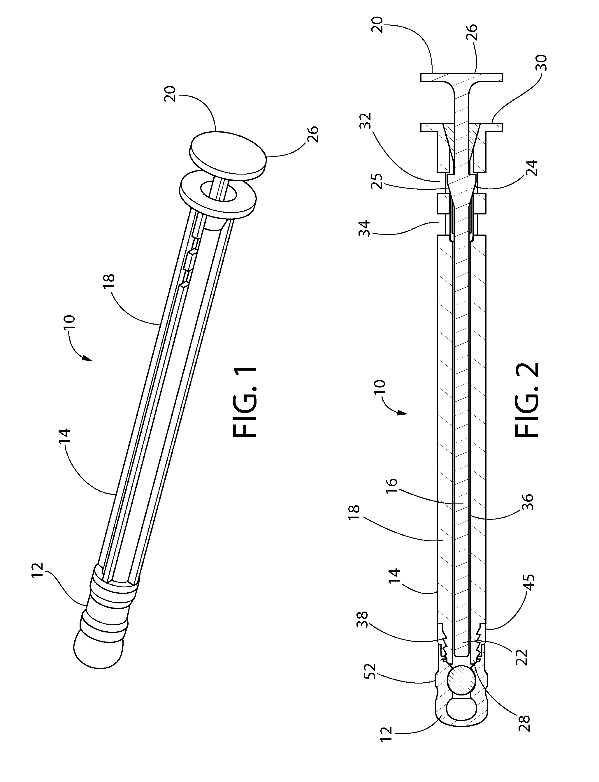
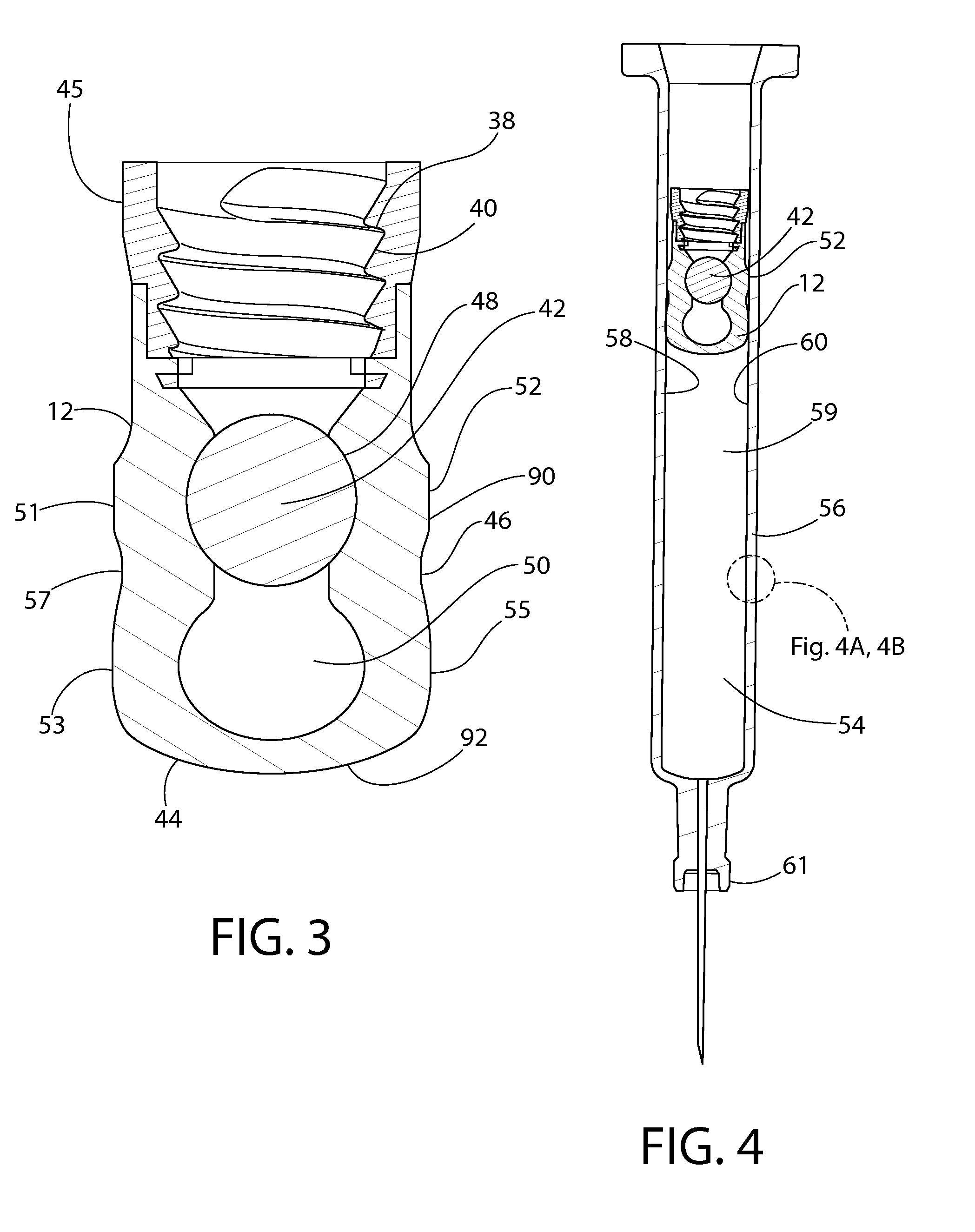
A convertible plunger is provided comprising an internal portion and a generally cylindrical exterior surface. At least a portion of the exterior surface is maintained in an initial expanded state by a property of the internal portion. The expanded state is reducible to a constricted state by an operation that is applied to the internal portion of the plunger to alter the property. A film coating may also be applied to a sidewall of the sleeve to reduce a sliding friction between the sleeve and barrel. A film coating may also be applied to a nose cone of the plunger to provide a barrier between the plunger and product in the barrel.

Description

CROSS-REFERENCE TO RELATED APPLICATIONS[0001]This application claims priority to U.S. Provisional Application Ser. No. 61 / 887,899, filed Oct. 7, 2013; 61 / 912,734, filed Dec. 6, 2013; 61 / 938,011, filed Feb. 10, 2014 and 62 / 048,675, filed Sep. 10, 2014.FIELD OF INVENTION[0002]The present invention relates generally to plungers and their use in drug delivery devices, such as (pre-filled, filled before use or empty) syringes, cartridges or auto-injectors. More particularly, the present invention relates to convertible plungers that provide and maintain container closure integrity in an expanded state or storage mode, during the shelf-life of a pre-filled syringe, and which are reducible to a constricted state or dispensing mode, when in use, to provide for relatively low and smooth plunger force when dispensing syringe contents.BACKGROUND[0003]The present disclosure predominantly describes use of plungers and plunger assemblies according to the present invention in connection with pre-f...

Claims


Application Information

Patent Timeline
Patent Type & Authority Applications(United States)
IPC IPC(8): A61M5/315A61L31/04A61L31/10
CPCA61M5/31513A61M5/31515A61M2205/0222A61M2205/0238A61M5/20A61M5/31511A61M5/31501A61L31/049A61L31/10A61L2420/08A61M5/3129
Inventor GIRAUD, JEAN-PIERRESOL, BERNARDPANGBORN, ROBERT J.ABRAMS, ROBERT S.ROGERS, JOSEPH W.SAGONA, PETER J.MIMS, MCHAEL J.
Owner SI02 MEDICAL PRODS
Learn More