

Fuel supply device
a fuel supply device and fuel supply technology, applied in the direction of liquid fuel feeders, machines/engines, charge feed systems, etc., can solve the problems of reduced productivity and complex assembly operation, and achieve the effect of suppressing pressure oscillations and reducing noise in the path from the fuel passage to the internal combustion engin
- Summary
- Abstract
- Description
- Claims
- Application Information
AI Technical Summary
Benefits of technology
Problems solved by technology
Method used
Image

Examples
first embodiment
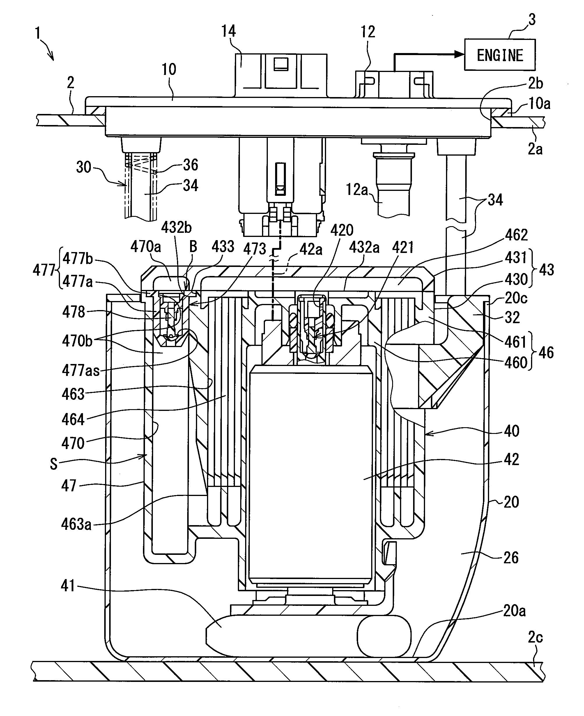
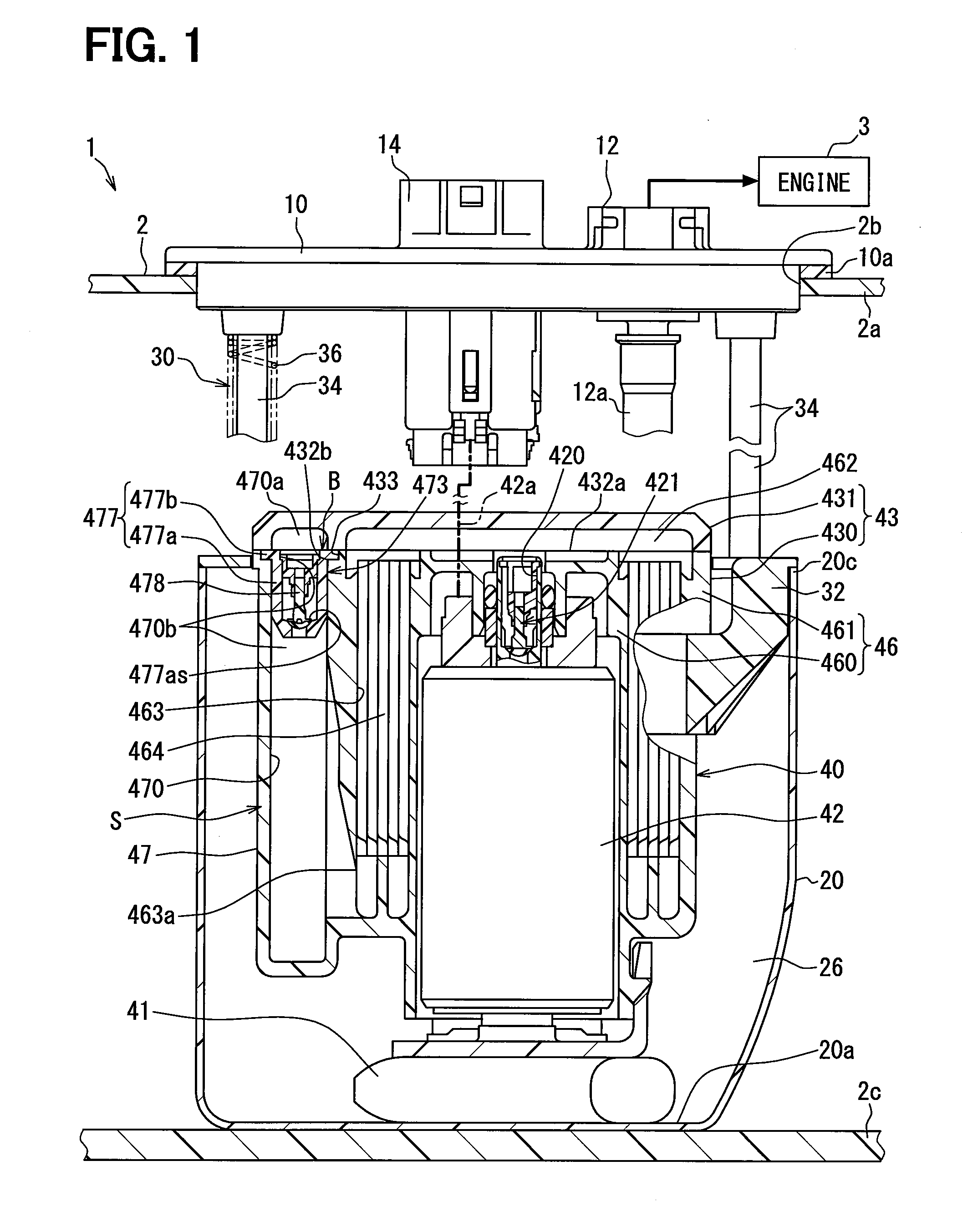
[0040]As shown in FIGS. 1 and 2, a fuel supply device 1 according to a first embodiment of the present disclosure is mounted in a fuel tank2 of a vehicle. The device 1 supplies, directly or indirectly through a high pressure pump etc., fuel inside the fuel tank 2 to fuel injection valves of an internal combustion engine 3. Here, the fuel tank 2 equipped with the device 1 is formed from resin or metal in a hollow shape, and stores fuel to be supplied to the internal combustion engine 3. Further, the engine 3 to which the device 1 supplies fuel may be a gasoline engine, or may be a diesel engine. In addition, the up and down direction of the device 1 shown in FIGS. 1 and 2 substantially matches the up and down direction of the vehicle when the vehicle is on a level surface.
[0041](Configuration and Operation)
[0042]Next, the configuration and operation of the device 1 will be explained.
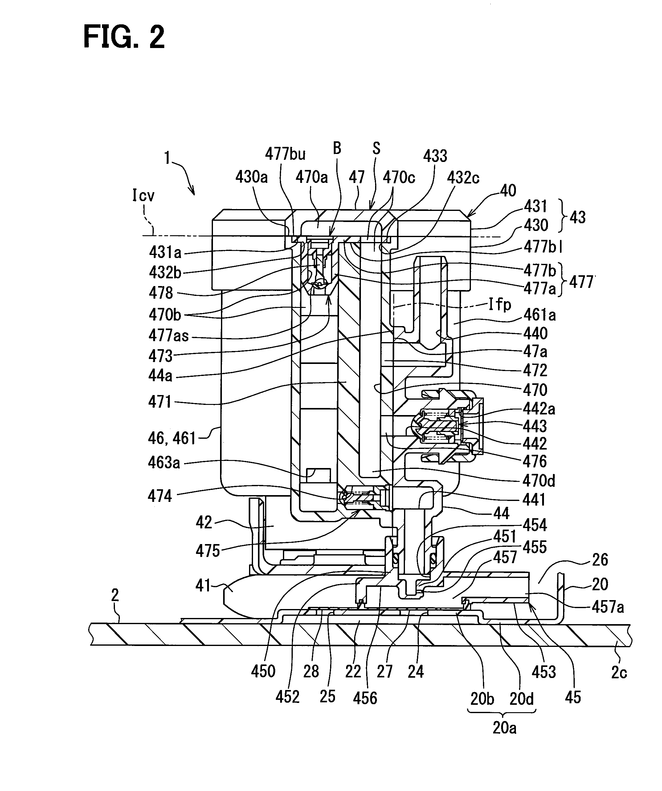
[0043]As shown in FIGS. 1 to 3, the device 1 includes a flange 10, a subtank 20, a regulating mechanis...
second embodiment
[0095]As shown in FIG. 5, a second embodiment of the present disclosure is a modified example of the first embodiment. In the second embodiment, a press fitting recess portion 2433 is formed as a flat shaped space at the opening periphery of the turning back portion 470a at the bottom portion of a case cap 2431. A joining plate 2477b of a valve housing 2477 is press fit into this press fitting recess portion 2433. Here, both a lower surface portion 2477bl and an upper surface portion 2477bu of the joining plate 2477b are formed in a planar shape. Due to this shape, the lower surface portion 2477bl is joined by fusing, on the common imaginary plane Icv, to the inner rim portion of the press fitting recess portion 2433 in a lower surface portion 2431a of the case cap 2431 and to an upper surface portion 2430a of a case body 2430. Due to these elements being press fit and joined in this manner, the joining plate 2477b, which is interposed between the case body 2430 and the case cap 243...
third embodiment
[0098]As shown in FIG. 7, a third embodiment of the present embodiment is a modified example of the first embodiment. A press fitting recess portion 3433 of the third embodiment is formed as a flat shaped space at only the periphery of the upstream aperture 432b, which is a location corresponding to the upstream straight portion 470b at the upper region of a case body 3430.
[0099]Further, according to a valve housing 3477 of the third embodiment, instead of the joining plate 477b, a joining flange 3477b is integrally formed together with the housing body 477a from resin. The joining flange 3477b, which continuously arranged on the upper region of the housing body 477a, is formed in an annular flange shape along the outer circumference of this body 477a. The joining flange 3477b is press fit into the press fitting recess portion 3433. Here, both an upper surface portion 3477bu and a lower surface portion 3477bl of the joining flange 3477b are formed in a planar shape. Due to this shap...
PUM
 Abstract
Description
Claims
Application Information