

Zero Optical Path Difference Phased Array
a phased array, zero optical path technology, applied in the direction of direction/deviation determining electromagnetic systems, instruments, optical elements, etc., can solve the problems of limited number of navigational stars that may be used, required precision, and substantial problems
- Summary
- Abstract
- Description
- Claims
- Application Information
AI Technical Summary
Benefits of technology
Problems solved by technology
Method used
Image

Examples
Embodiment Construction
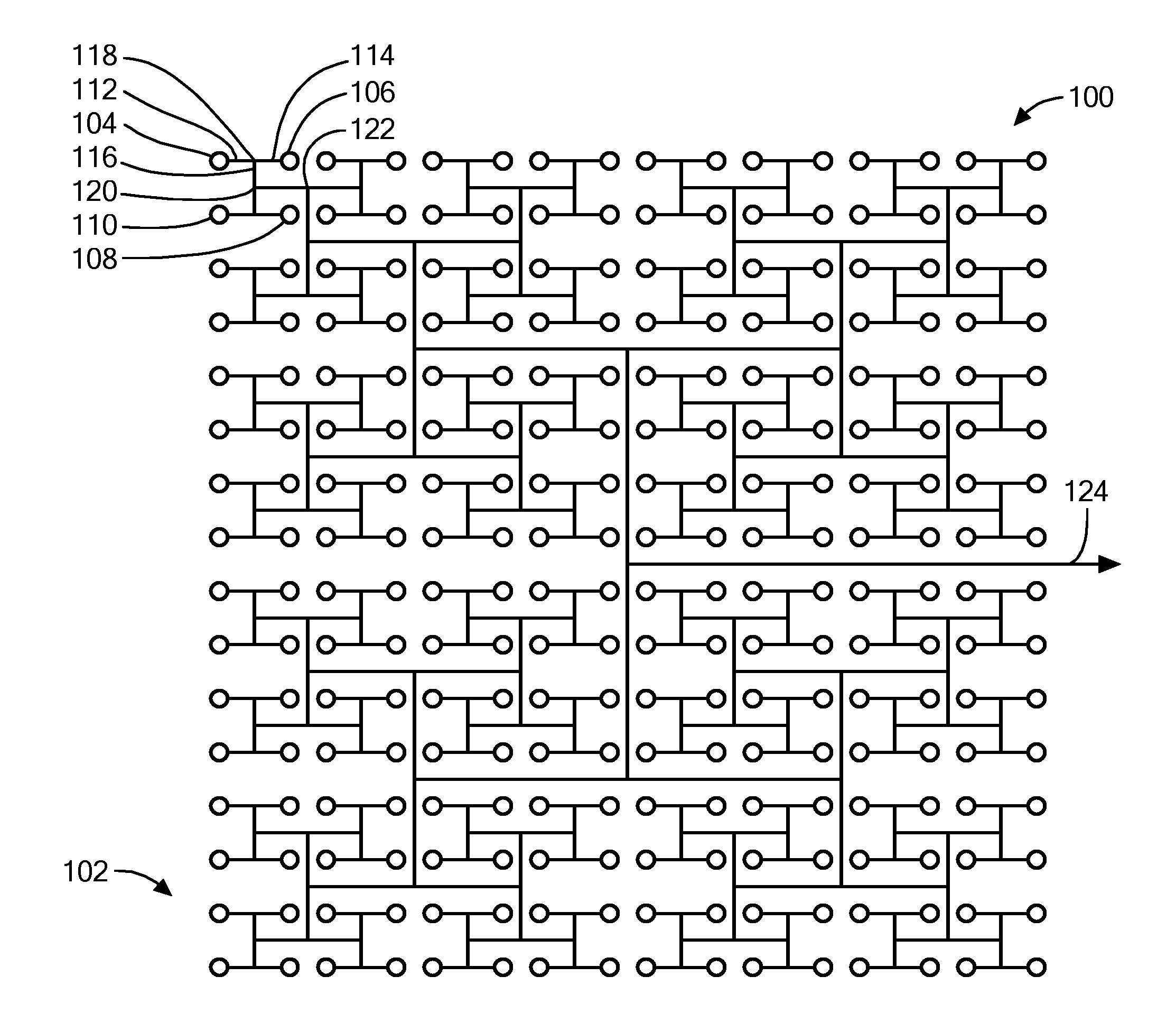
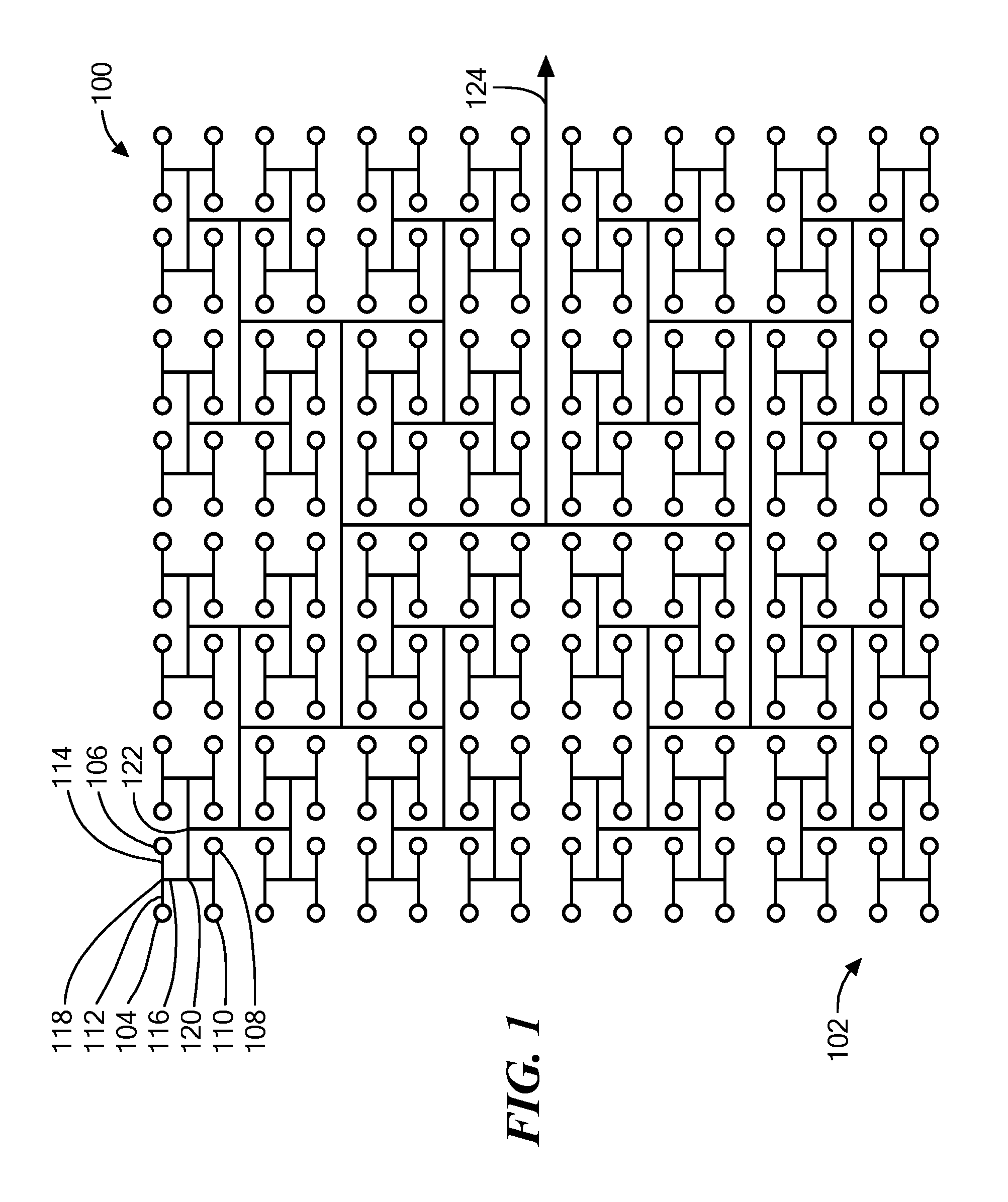
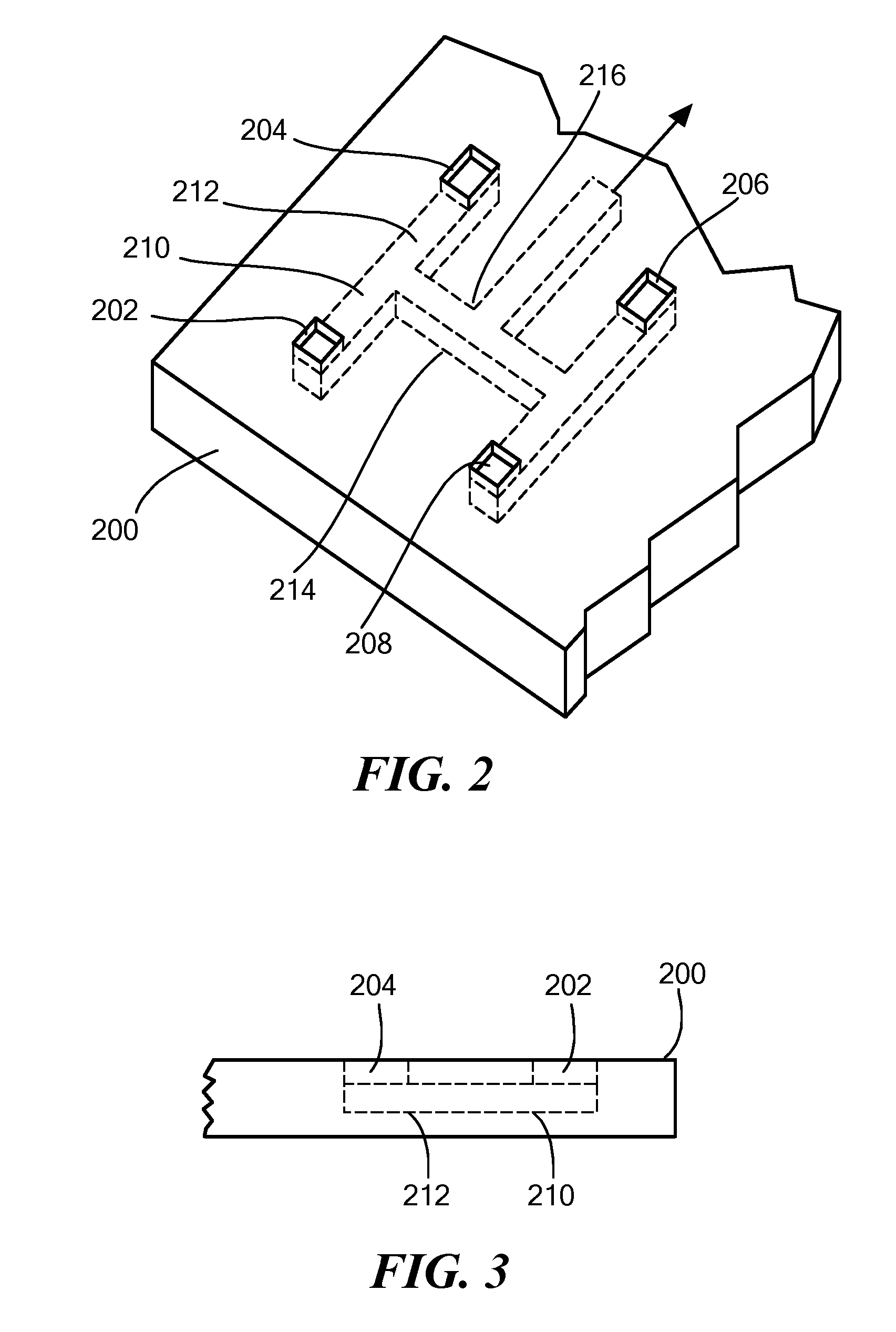
[0008]An embodiment of the present invention provides an optical phased array. The optical phased array has a design wavelength. The design wavelength is between about 100 nm and about 1 mm. The optical phased array also has a design bandwidth. The optical phased array includes a wafer. A first plurality of optical couplers is disposed in a predefined array, relative to the wafer. A first optical port is disposed in a predefined location, relative to the wafer.
[0009]A first plurality of optical waveguides is disposed relative to the wafer. The first plurality of optical waveguides optically connects the first plurality of optical couplers to the first port via respective first optical paths. There is one first optical path per first optical coupler. Optical lengths of all the first optical paths are equal, within a criterion. The criterion may be one coherence length at a bandwidth greater than about 0.1% plus a spacing between two maximally spaced-apart optical couplers of the firs...
PUM
 Abstract
Description
Claims
Application Information