Printing apparatus
a technology of printing apparatus and printing belt, which is applied in the direction of printing press, thin material handling, printing, etc., can solve the problems of reducing the tension of the transport belt, affecting and foreign matter that is detached from the destaticization section, so as to achieve the effect of suppressing the reduction of the removal efficiency of electric charges
- Summary
- Abstract
- Description
- Claims
- Application Information
AI Technical Summary
Benefits of technology
Problems solved by technology
Method used
Image
Examples
first embodiment
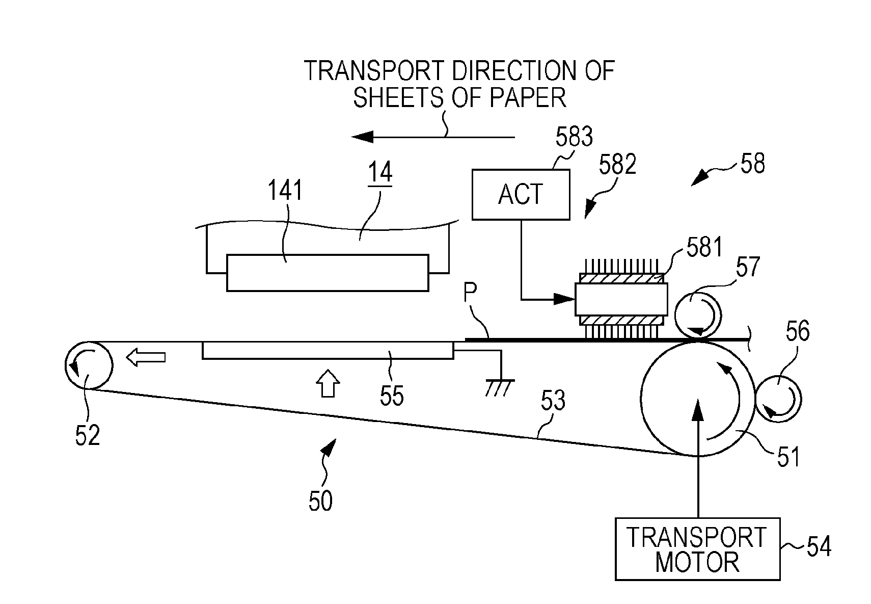
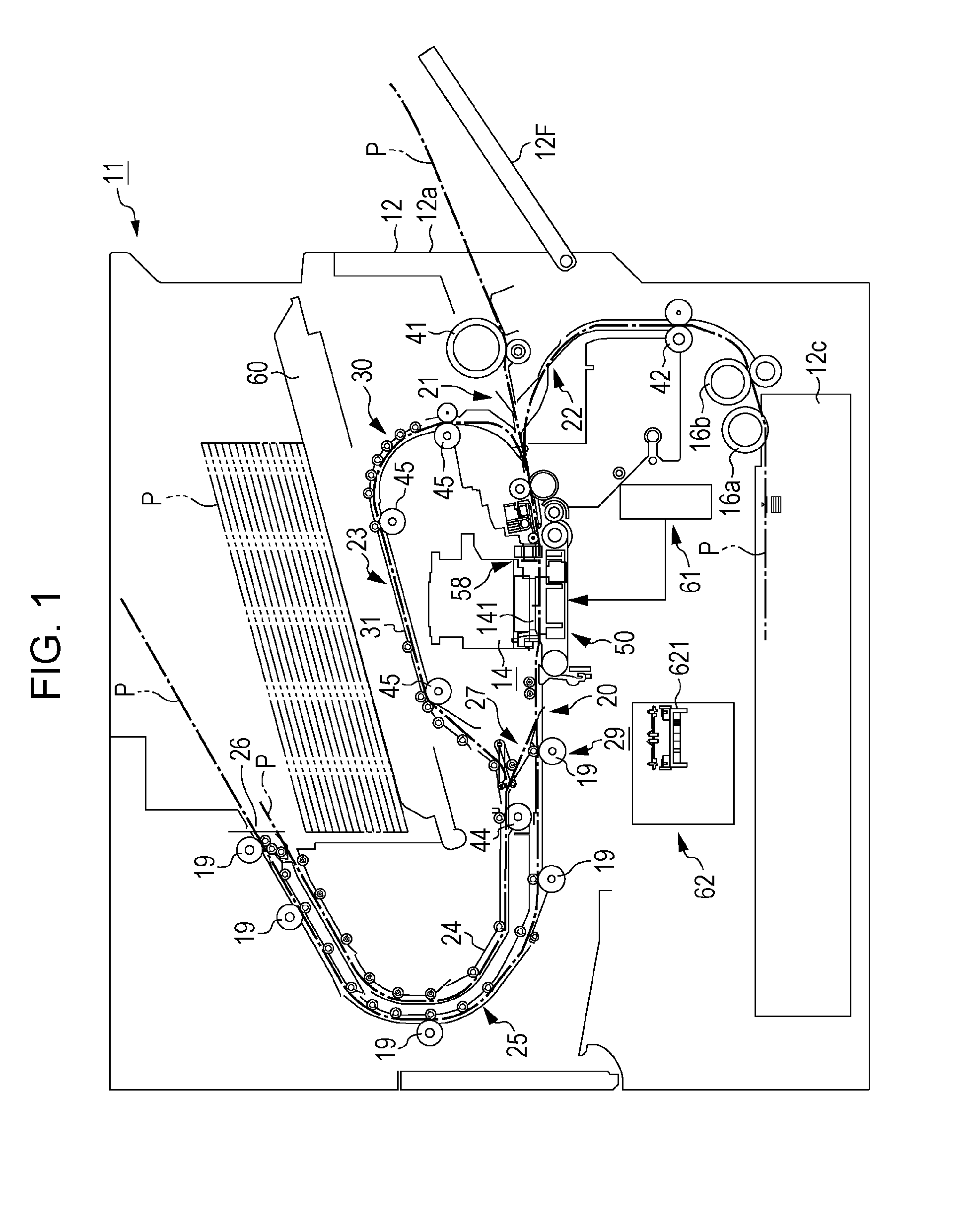
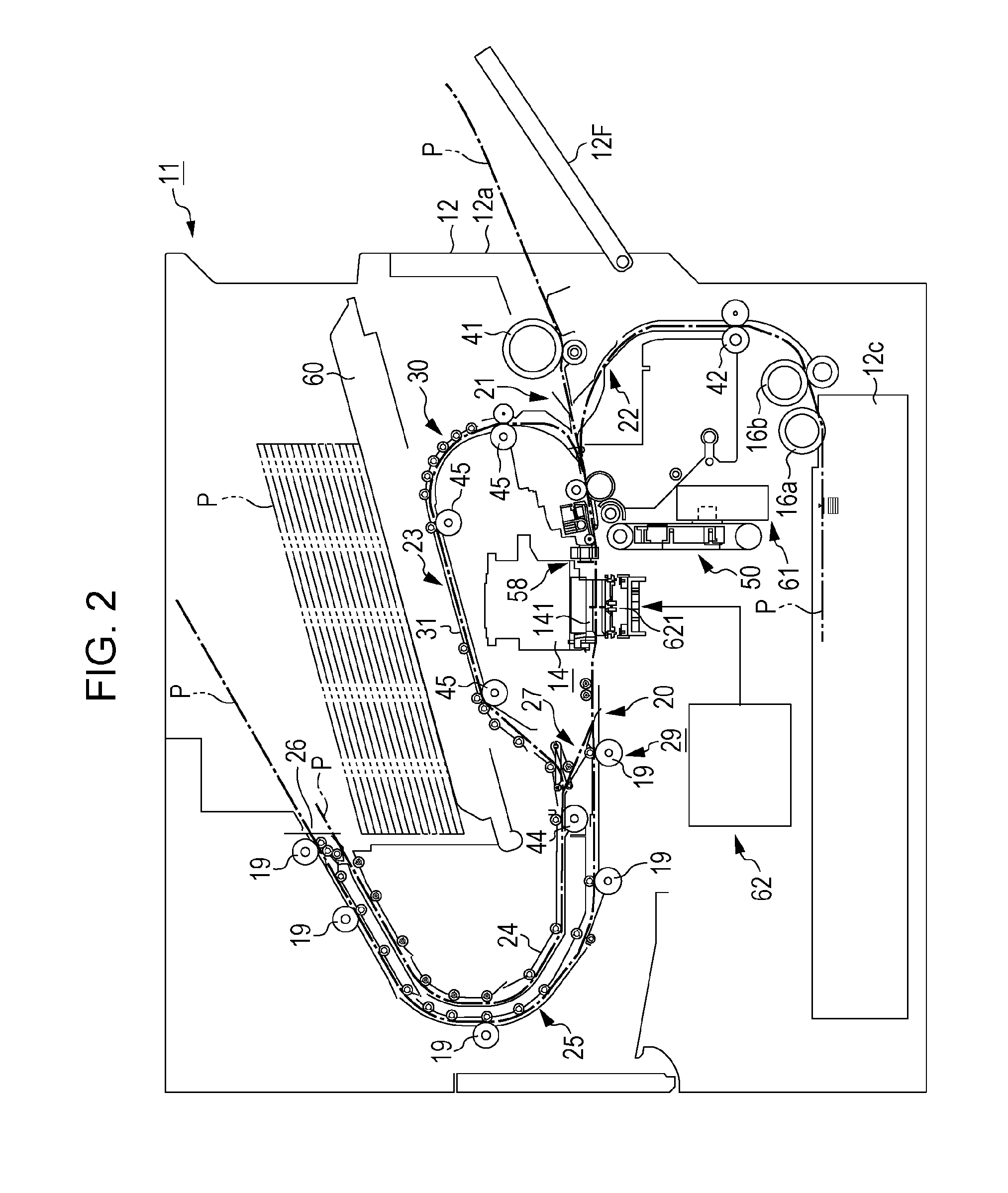
[0070]Hereinafter, a first embodiment in which a printing apparatus takes the form of an ink jet type printer, will be described in accordance with FIGS. 1 to 10.
[0071]As shown in FIG. 1, a transport device 29 that transports sheets of paper P, which are an example of a printing medium, along a medium transport path 20, and a printing unit 14 that carries out printing on sheets of paper P that are transported, are provided inside a housing 12 of a printing apparatus 11 the present embodiment. In a case in which a direction that is orthogonal a paper surface in FIG. 1 is set as a width direction of sheets of paper, the medium transport path 20 is formed so as to transport sheets of paper P in a direction that intersects the width direction of sheets of paper, and desirably a direction that is orthogonal to the width direction.
[0072]The printing unit 14 is provided with a line head type printing head 141 that is capable of discharging an ink, which is an example of a printing material...
second embodiment
[0129]Next, a second embodiment in which the printing apparatus 11 is given a specific form, will be described in accordance with FIG. 11. Additionally, in the second embodiment, the timing with which the operation process is implemented differs from that of the first embodiment. Accordingly, in the following description, description will be given focusing on portions that differ from the first embodiment, the same reference numerals will be given to member configurations that are the same as those of the first embodiment, and overlapping descriptions thereof will be omitted.
[0130]A process sequence when the destaticization section 581 is operated will be described with reference to the flowchart that is shown in FIG. 11.
[0131]As shown in FIG. 11, in Step S21, it is determined whether or not it is immediately after printing based on a single printing job has been completed. Further, in a case in which it is immediately after the completion of printing (Step S21: YES), the process th...
third embodiment
[0135]Next, a third embodiment in which the printing apparatus 11 is given a specific form, will be described in accordance with FIG. 12. Additionally, in the third embodiment, the timing with which the operation process is implemented differs from that of each embodiment of the first and second embodiments. Accordingly, in the following description, description will be given focusing on portions that differ from each embodiment of the first and second embodiments, the same reference numerals will be given to member configurations that are the same as those of each embodiment of the first and second embodiments, and overlapping descriptions thereof will be omitted.
[0136]In the printing apparatus 11 of the present embodiment, a plurality of printing modes, in which the resolution of an image that is formed on the printing surface Pb of sheets of paper P differs, are prepared. For example, a first printing mode is a mode for forming a high resolution image on the printing surface Pb b...
PUM
| Property | Measurement | Unit |
|---|---|---|
| distance L2 | aaaaa | aaaaa |
| distance L2 | aaaaa | aaaaa |
| distance | aaaaa | aaaaa |
Abstract
Description
Claims
Application Information
 - R&D
- Intellectual Property
- Life Sciences
- Materials
- Tech Scout
- Unparalleled Data Quality
- Higher Quality Content
- 60% Fewer Hallucinations
Browse by: Latest US Patents, China's latest patents, Technical Efficacy Thesaurus, Application Domain, Technology Topic, Popular Technical Reports.
© 2025 PatSnap. All rights reserved.Legal|Privacy policy|Modern Slavery Act Transparency Statement|Sitemap|About US| Contact US: help@patsnap.com


