System for measuring the yaw, spin and muzzle velocity of an ammunition projectile

a projectile and spin-driven technology, applied in the field of system for measuring the yaw, spin-driven muzzle velocity of an ammunition projectile, can solve the problems of inability to readily incorporate high-speed imaging and laboratory methodologies and equipment which are presently used to determine and measure yaw in operational weapons, the difficulty of measuring projectile yaw and/or determining projectile motion, etc., to improve the accuracy and accuracy of aiming, improve the effect of accuracy and ballistic prediction

Inactive Publication Date: 2016-09-01
NOSTROMO HLDG LLC
View PDF1 Cites 1 Cited by
  • Summary
  • Abstract
  • Description
  • Claims
  • Application Information

AI Technical Summary

Benefits of technology

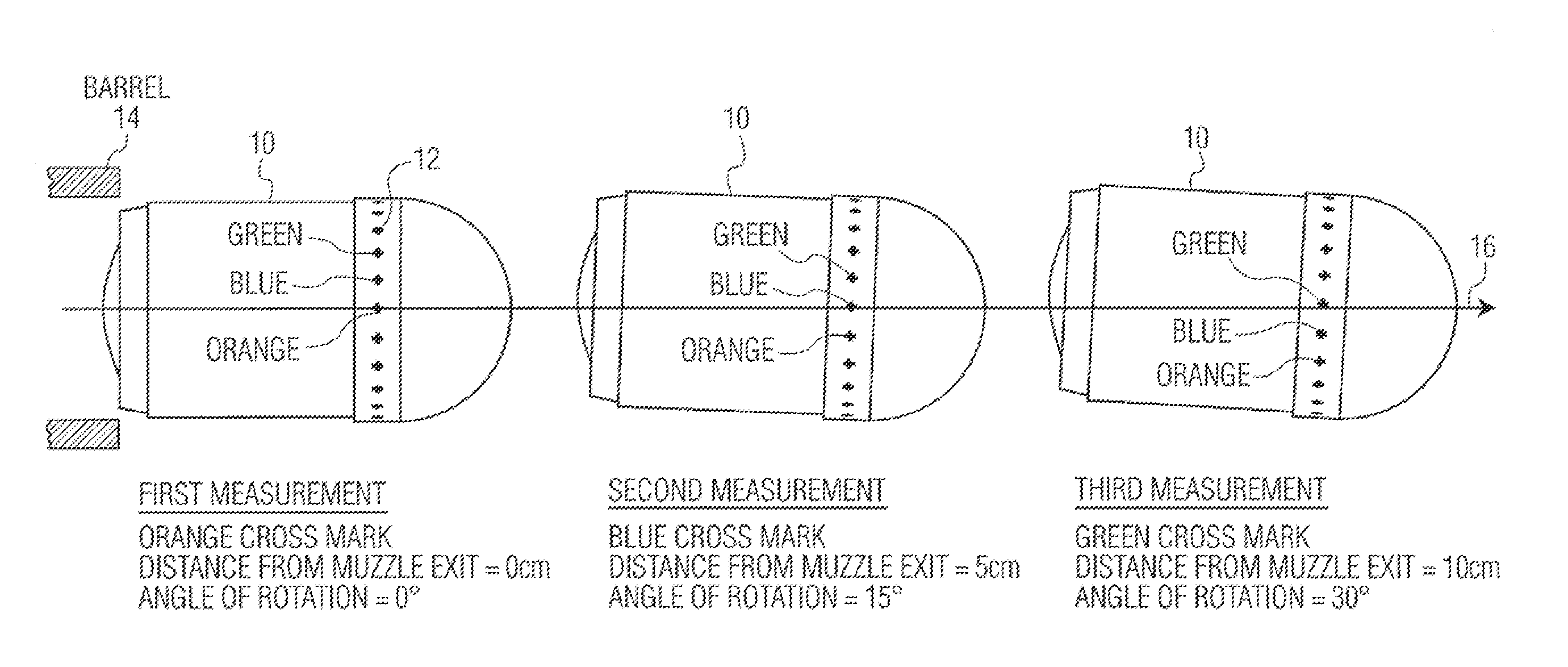
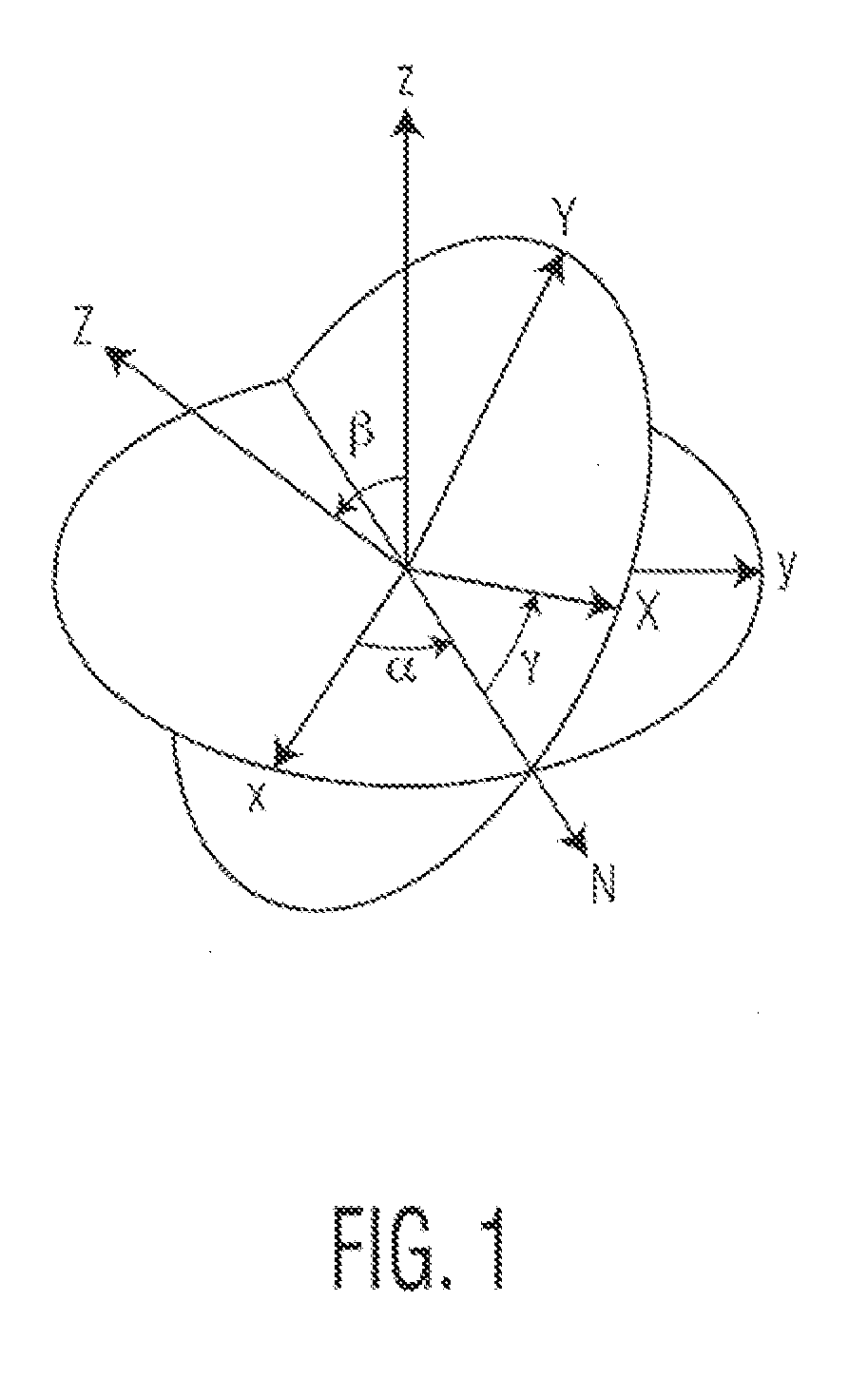
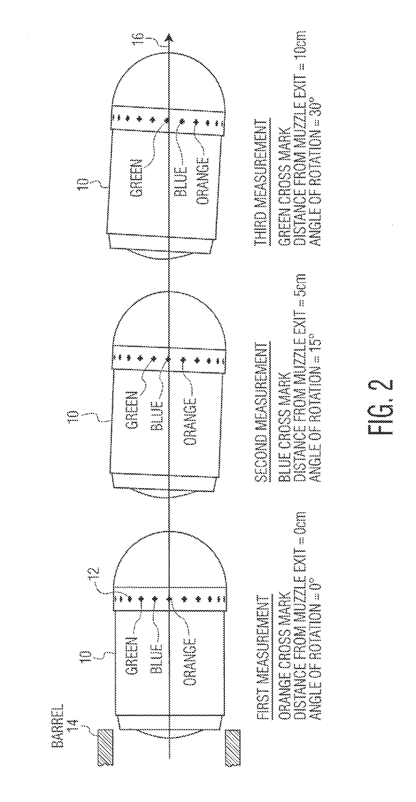
[0037]To measure the motion parameters (muzzle velocity, spin and axis rotation (yaw) as well a acceleration/de-acceleration of the projectile, the projectile is illuminated two or more times as it exits the barrel thru the muzzle of the weapon. After each illumination and image capture, the positions of the projectile's indexing marks are determined and stored. The illumination sequence is repeated at known elapsed times following barrel exit. As a result, this process allows for accurate determination of the yaw, spin and muzzle velocity, as well as any acceleration/de-acceleration of the projectile in a compact device.
[0038]Recorded projectile measurements are then transmitted to a fire control sate. (internal or external to the flash suppressor or muzzle break). This allows the fire control computer to classify the projectile's performan

Problems solved by technology

While fire control systems have proved as sensor fidelity, electronic miniaturization and improvements in computational capabilities came of age, the inability to measure projectile yaw in operational weapons remains an unsolved problem that stands in the way of improvements in the precision aiming of firearms and weapons.
Specialized high-speed imaging and laboratory methodologies and equipment which are presently used to determine and measure y

Method used


Image

  • System for measuring the yaw, spin and muzzle velocity of an ammunition projectile
  • System for measuring the yaw, spin and muzzle velocity of an ammunition projectile
  • System for measuring the yaw, spin and muzzle velocity of an ammunition projectile

Examples


Embodiment Construction

[0056]The preferred embodiments of the invention will now be described with reference to FIGS. 1-16 of the drawings. Identical elements in the various figures have been designated with the same reference numerals.

[0057]The system according to the invention utilizes the following components:

[0058]Projectiles provided with high contrast markings (e.g. color dyed) which may include luminescent characteristics.

[0059]Strobe illumination of the projectiles as they exit the barrel of a gun and pass through a flash suppressor or muzzle break.

[0060]Imagers that capture positions of the projectile markings. Three measurement points are desired so that the rates of change of the parameters can be measured.

[0061]Optical measurements are captured and recorded, preferably from multiple angles to confirm the rotation axis.

[0062]A computer with a signal processor, coupled to the imagers, determines the locations of the projectile markings at successive instants of time and computes and records the ...


PUM


Abstract

An ammunition projectile has a plurality of distinctive marks arranged in at least one circular row around the projectile body, with the row of marks extending perpendicular to its longitudinal axis. The marks are illuminated by a strobe flash and successive images are captured by an electronic imager as the projectile exits the barrel of a weapon. A computer, coupled to the imager, processes the electron is signals to determine projectile yaw, spin and muzzle velocity.

Description

CROSS REFERENCE TO RELATED APPLICATION[0001]This application claims priority from the U.S. Provisional Application No. 61 / 805,534 filed Mar. 27, 2013.BACKGROUND OF THE INVENTION[0002]While fire control systems have proved as sensor fidelity, electronic miniaturization and improvements in computational capabilities came of age, the inability to measure projectile yaw in operational weapons remains an unsolved problem that stands in the way of improvements in the precision aiming of firearms and weapons.[0003]Specialized high-speed imaging and laboratory methodologies and equipment which are presently used to determine and measure yaw cannot be readily incorporated into fire arms and weapons used in the field.[0004]As a projectile exits a barrel it enters a “dirty” environment that obscures simple detection due to the wash of gases from the propellant (smoke, powder residue, un-burnt powder and bright illumination from the propellant burn). This situation adds to the difficulty of mea...

Claims


Application Information

Patent Timeline
IPC IPC(8): F42B12/40G01P3/68
CPCG01P3/685F42B12/40F41G3/12F42B5/025F42B35/00F41A21/32
Inventor SULLIVAN, KEVIN MICHAELMARTINEZ, MARCELO EDUARDO
Owner NOSTROMO HLDG LLC
Why Eureka
Try Eureka